
Mobile robot

a robot and robot body technology, applied in the field of mobile robots, can solve the problems of not ensuring reliable accuracy in sensing a distance from an obstacle, or sensing a floor condition in a cleaning area, such as a cliff, and achieve the effect of ensuring reliable accuracy

Active Publication Date: 2015-04-30
LG ELECTRONICS INC
View PDF7 Cites 54 Cited by
  • Summary
  • Abstract
  • Description
  • Claims
  • Application Information

AI Technical Summary

Benefits of technology

The patent describes a mobile robot that can create an optical pattern around itself using a pattern irradiation unit. This unit includes a light source and a lens with special cells that convert the light from the source into the pattern. The lens has two areas, each with its own set of cells. The first area creates a line in the first direction and the second area creates a line in the second direction that intersects with the first line. This robot can create precise and accurate paths for itself and can also help other robots navigate their surroundings.

Problems solved by technology

These sensors assure some degree of accuracy in sensing whether or not an obstacle is present on a traveling path, but do not assure reliable accuracy in sensing a distance from an obstacle or sensing a floor condition in a cleaning area, such as a cliff.

Method used


Image

  • Mobile robot
  • Mobile robot
  • Mobile robot

Examples


Embodiment Construction

[0030]The advantages and features of the present invention, and the way of attaining them, will become apparent with reference to embodiments described below in conjunction with the accompanying drawings. Reference will now be made in detail to the preferred embodiments of the present invention, examples of which are illustrated in the accompanying drawings. Wherever possible, the same reference numbers will be used throughout the drawings to refer to the same or like parts.

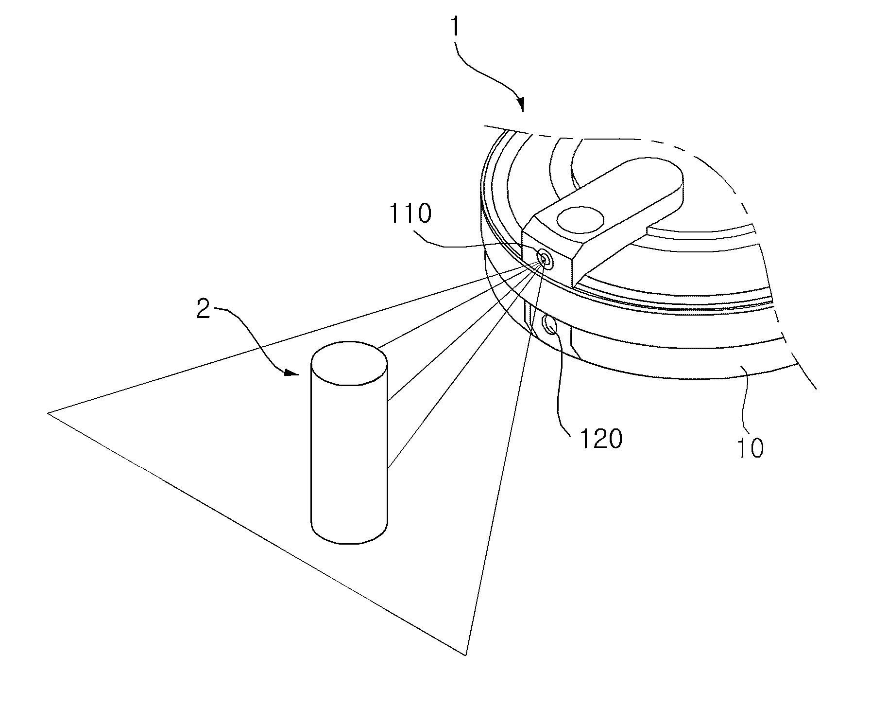
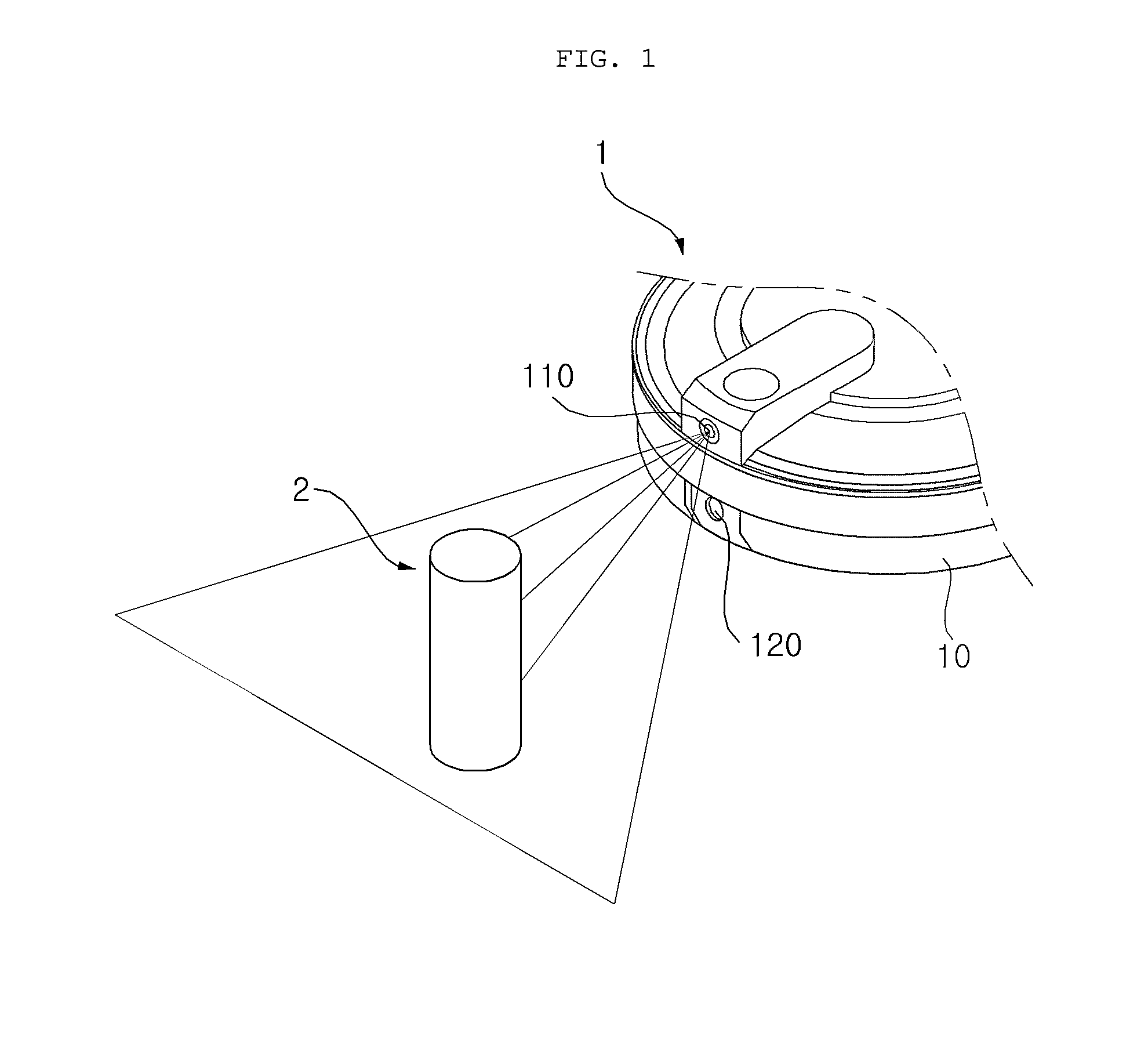
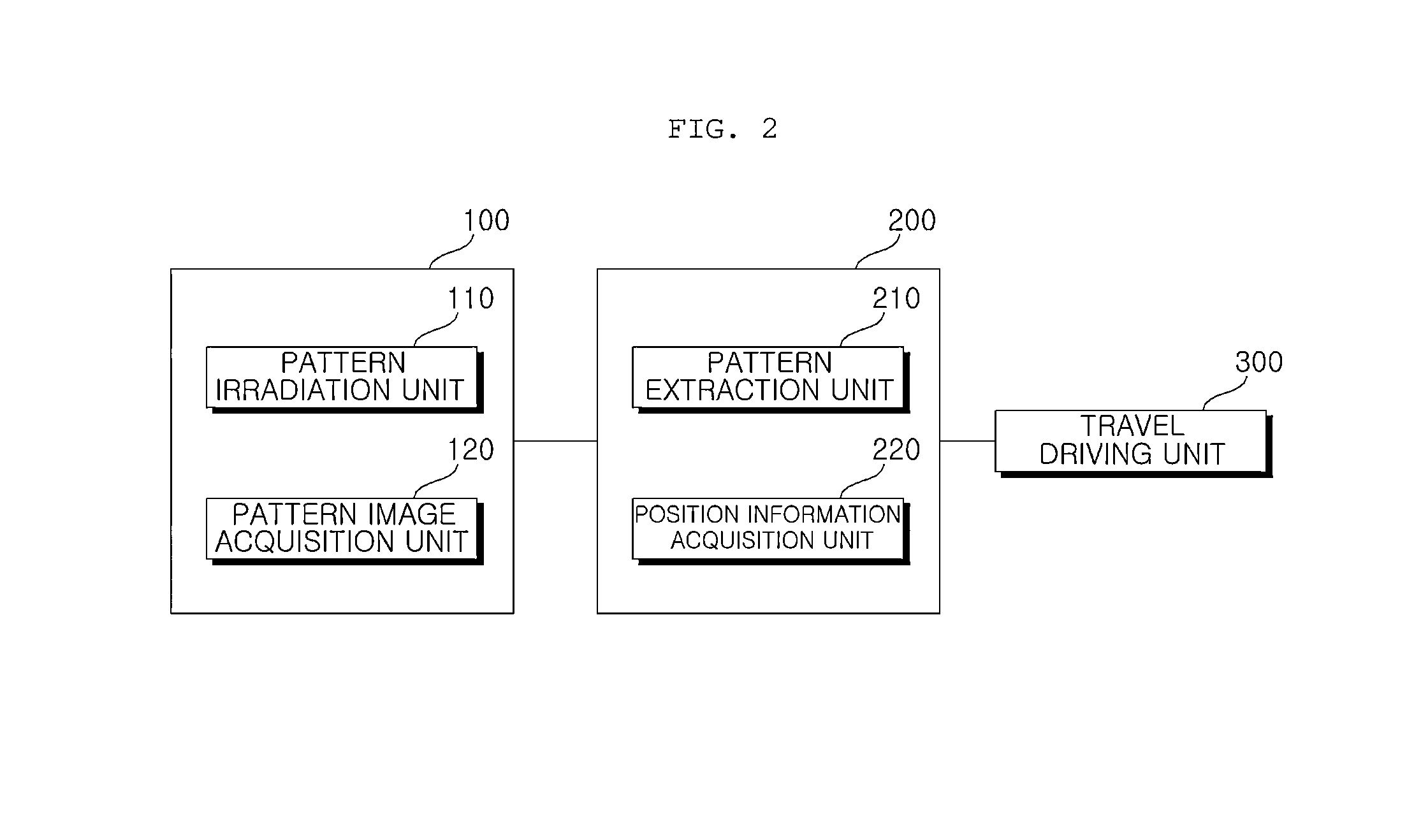
[0031]FIG. 1 is a perspective view illustrating a portion of a mobile robot in accordance with one embodiment of the present invention and FIG. 2 is a block diagram schematically illustrating the configuration of a mobile robot in accordance with one embodiment of the present invention.

[0032]With reference to FIGS. 1 and 2, a mobile robot in accordance with one embodiment of the present invention includes a mobile main body 10, an optical pattern sensor 100, and a controller 200.

[0033]The optical pattern sensor 1...


PUM


Abstract

Disclosed is a mobile robot including a main body and a pattern irradiation unit emitting a cross-shaped optical pattern including a horizontal line optical pattern and a vertical line optical pattern intersecting the horizontal line optical pattern. The pattern irradiation unit includes a light source and a lens converting light emitted from the light source into the cross-shaped optical pattern, the lens includes convex cells on an incidence surface upon which the emitted light is incident, the incidence surface is divided into a first area converting the light emitted from the light source into the horizontal line optical pattern and a second area converting the light emitted from the light source into the vertical line optical pattern, vertical convex cells extended in parallel in the vertical direction are formed in the first area, and horizontal convex cells extended in parallel in the horizontal direction are formed in the second area.

Description

CROSS-REFERENCE TO RELATED APPLICATION[0001]This application claims the benefit of Korean Patent Application No. 10-2013-0131622, filed on Oct. 31, 2013 in the Korean Intellectual Property Office, the disclosure of which is incorporated herein by reference.BACKGROUND OF THE INVENTION[0002]1. Field of the Invention[0003]The present invention relates to a mobile robot detecting an obstacle using an optical pattern.[0004]2. Description of the Related Art[0005]In general, robots developed for industry are applied to factory automation. Recently, application fields of robots are expanding and not only medical robots and aerospace robots but also home robots used in general homes have been developed.[0006]As a representative example of home robots, there is a robot cleaner. The robot cleaner is a kind of home appliance which autonomously travels about a cleaning area and absorbs foreign substances to clean the area. Generally, the robot cleaner spontaneously travels using a rechargeable b...

Claims


Application Information

Patent Timeline
IPC IPC(8): B25J9/16H04N5/74G01S17/931
CPCB25J9/1676Y10S901/01B25J9/1697H04N5/74G05D1/024A47L2201/04G01S17/46G01S7/4814G01S17/931B25J9/10B25J13/08
Inventor NOH, DONGKIBAEK, SEUNGMINKU, YOUNGUK
Owner LG ELECTRONICS INC
Learn More