Non-traversing tube inspection system

a tube inspection and non-traversing technology, applied in the direction of analyzing solids using sonic/ultrasonic/infrasonic waves, sensors, diagnostics, etc., can solve the problem of difficult to determine through apr whether an increase in cross section is possible, and the gw method may have difficulties in distinguishing between pits and through holes

Active Publication Date: 2015-05-07
ARISE GLOBAL PTE LTD
View PDF8 Cites 5 Cited by
  • Summary
  • Abstract
  • Description
  • Claims
  • Application Information

AI Technical Summary

Benefits of technology

[0025]It should be appreciated that some embodiments are configured to implement the GW technique without the APR modality. In such embodiments, after inserting the probe into an inspected tube, an example embodiment of a GW system may transmit mechanical waves in the tube wall. The mechanical waves can be, but are not limited to, torsional or longitudinal waves. The excitation signal can be, for example but is not limited to, a pulse or a pseudo-noise signal, swept sine, etc. Any changes in the tube wall properties or dimensions will create a reflection which can be recorded and analyzed.

Problems solved by technology

Small pits in the tube wall create relatively small changes in the cross section profile of a tube, thus making the reflected signals small and therefore hard to detect.
Furthermore, because APR detects overall changes in the cross section of the tube, it is difficult to determine through APR whether an increase in cross section is created by a deep and narrow pit or by a shallow pit spread over a large portion of the circumference of the tube.
GW methods may have difficulties in distinguishing between pits and through holes, as well as distinguishing these from blockages in the tube.
When inspecting narrow gauge tubes such as those typically found in heat exchangers, it is difficult to fit a sufficient number of sensors into the limited space available.

Method used


Image

  • Non-traversing tube inspection system
  • Non-traversing tube inspection system
  • Non-traversing tube inspection system

Examples


Embodiment Construction

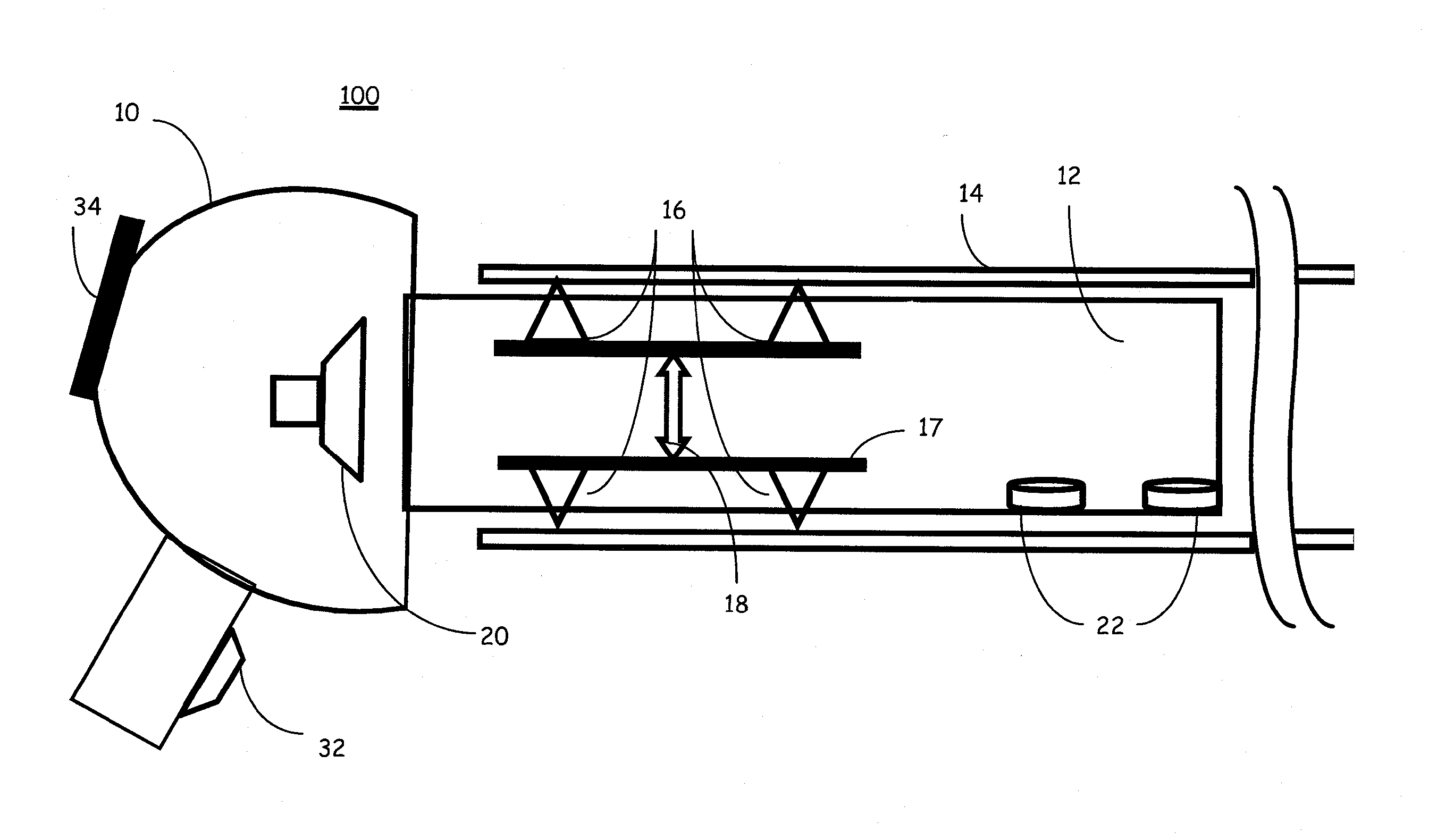
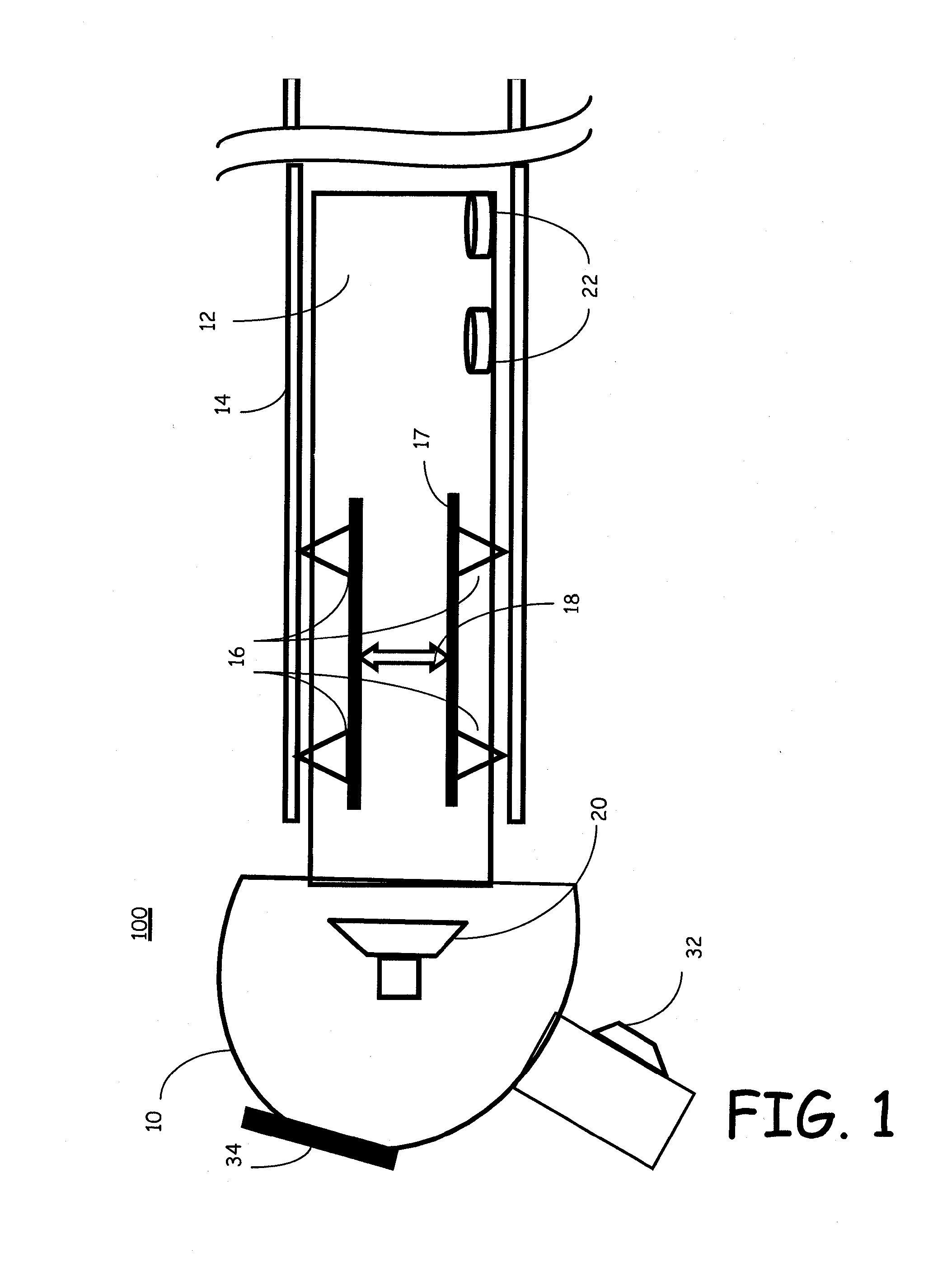
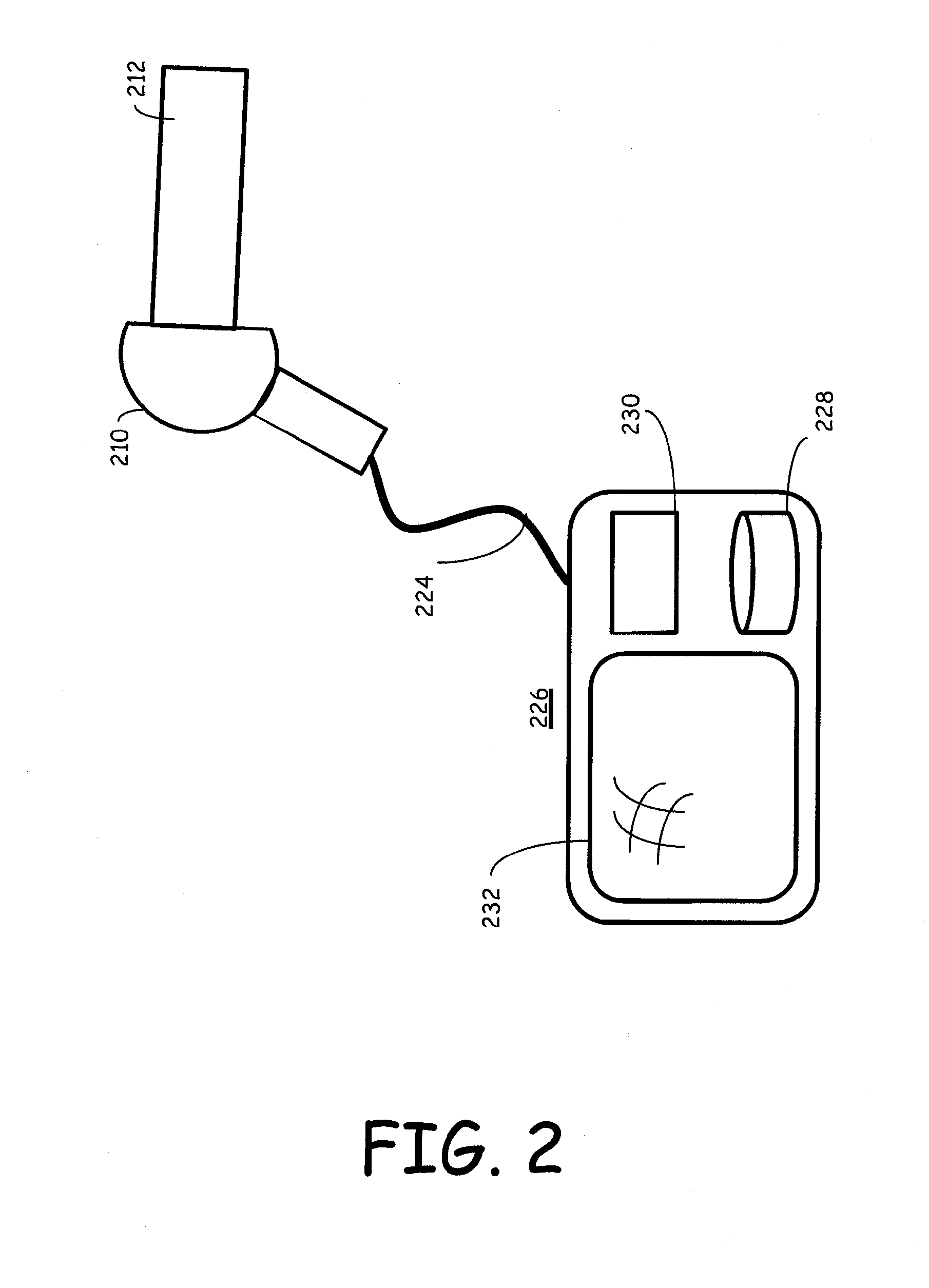
[0034]Turning now to the figures in which like numerals represent like elements throughout the several views, different embodiments of the tube inspection system, as well as features, aspects and functions that may be incorporated into one or more such embodiments, are described. For convenience, only some elements of the same group may be labeled with numerals. The purpose of the drawings is to describe different embodiments and not for production. Therefore features shown in the figures are chosen for convenience and clarity of presentation only. It should be noted that FIGS. 1, 2 and 3a&b are for illustration purposes only and are not drawn to scale. Moreover, the language used in this disclosure has been principally selected for readability and instructional purposes, and may not have been selected to delineate or circumscribe the inventive subject matter, resort to the claims being necessary to determine such inventive subject matter.

[0035]FIG. 1 illustrates an example of a han...


PUM

PropertyMeasurementUnit
lengthaaaaaaaaaa
diameteraaaaaaaaaa
diameteraaaaaaaaaa

Abstract

Tube inspections are performed by combining the use of APR technology with GW technology. The reflections measured by both technologies are compared to each other and used to more specifically identify the type and location of a flaw or anomaly that appears in the interior of the tube. Further, embodiments of novel probes to be used in GW technique for inspecting tubes with mechanical waves having bandwidth that is equal to 150 KHz or more are disclosed.

Description

CROSS-REFERENCE TO RELATED APPLICATIONS[0001]This application is being filed under the Patent Cooperation Treaty application and is being filed in the Israeli Receiving Office claiming the benefit of the prior filing date of the U.S. provisional application for patent that was filed on Jun. 11, 2012 bearing the tile of “MULTI-MODALITY NON-TRAVERSING TUBE INSPECTION SYSTEM,” and assigned Ser. No. 61 / 658,038. Further, this application claims the benefit of the prior filing date of the U.S. provisional application for patent that was filed on Feb. 11, 2013 bearing the tile of “MULTI-MODALITY NON-TRAVERSING TUBE INSPECTION SYSTEM,” and assigned Ser. No. 61 / 763,456.FIELD OF INVENTION[0002]The present invention relates to the field of non-destructive testing and more particularly, the present invention is in the technical field of non-traversing techniques for tube inspection.DESCRIPTION OF BACKGROUND ART[0003]There are several techniques presently in use for conducting tube inspections. ...

Claims


Application Information

Patent Timeline
Patent Type & Authority Applications(United States)
IPC IPC(8): G01N29/04G01N29/24
CPCG01N29/043G01N2291/2636G01N2291/044G01N29/24G01M5/0033G01M5/0066G01N2291/0425
Inventor AMIR, NOAMFURMAN, DOVPRIMACK, HARELZILBERMAN, SILVIU
Owner ARISE GLOBAL PTE LTD
Why Eureka
Try Eureka