Rotorcraft fuselage structure incorporating a load-bearing middle floor interposed between a cabin space and an equipment space

a fuselage structure and equipment space technology, applied in the field of aircraft fuselage structures, can solve the problems of difficult access to the bottom section, difficult to use the same equipment floor for all potential flight missions of rotorcraft, etc., and achieve the effects of easy interchangeability, increased protection of people, and convenient installation and use of heavy equipmen

Active Publication Date: 2015-05-07
EUROCOPTER
View PDF2 Cites 14 Cited by
  • Summary
  • Abstract
  • Description
  • Claims
  • Application Information

AI Technical Summary

Benefits of technology

[0048]For example, the middle floor is suitable for constituting a plane for fastening modular elements that may be arranged as slabs that have previously been fitted out for receiving specific pieces of equipment depending on the flight mission of the rotorcraft. Such slabs may constitute a false-floor that is easily interchangeable by selectively replacing slabs. In addition, such a false-floor can easily be raised relative to the top face of the middle floor in order to provide passages for said long elements.
[0049]Also by way of example, the middle floor is suitable for enabling the bottom compartment to present a vertical extent that may be significant, depending on the flight missions of the rotorcraft, by benefiting from the ease with which the bottom compartment can be accessed from outside the rotorcraft through the open bottom of the rotorcraft formed in the bottom face of the fuselage that does not have the covering, at least in its middle segment.
[0050]Access to the bottom compartment from the bottom face of the fuselage through said open bottom of the bottom compartment may be used to advantage for facilitating the installation and maintenance of fuel tanks received in the bottom compartment and anchored by being suspended from the bottom face ...

Problems solved by technology

The variety of flight missions makes it difficult to use the same equipment floor for all potential flight missions of a rotorcraft.
Nevertheless, accessi...

Method used


Image

  • Rotorcraft fuselage structure incorporating a load-bearing middle floor interposed between a cabin space and an equipment space
  • Rotorcraft fuselage structure incorporating a load-bearing middle floor interposed between a cabin space and an equipment space

Examples


Embodiment Construction

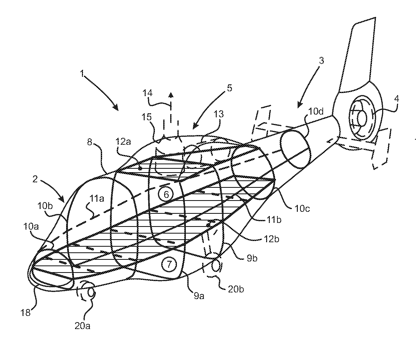
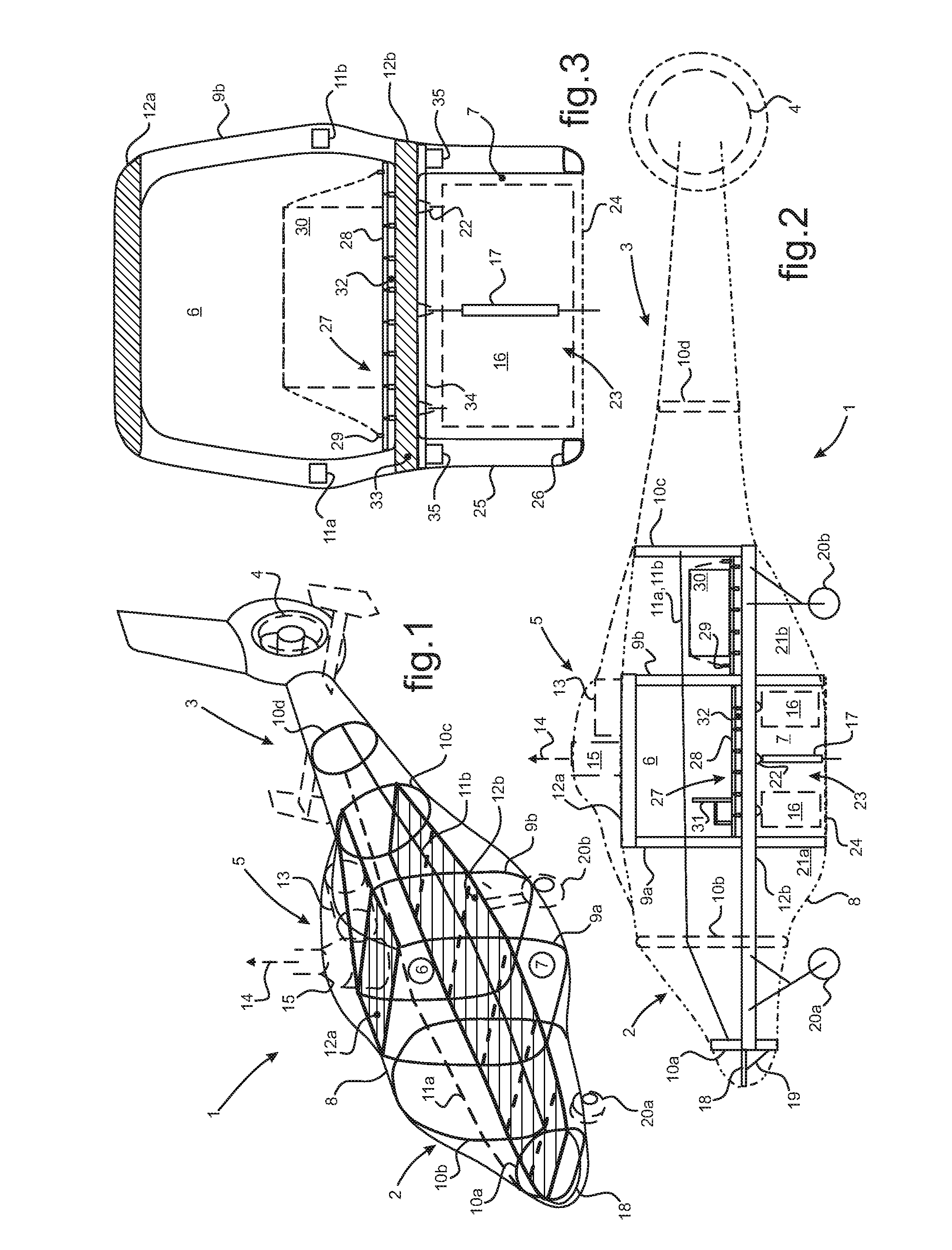
[0090]In FIGS. 1 and 2, a rotorcraft 1 comprises longitudinally a cockpit 2 situated at the front and a tail boom 3 supporting and anti-torque device 4, such as a tail rotor, for example. The cockpit 2 and the tail boom 3 are spaced apart from each other longitudinally by a middle segment 5 of the fuselage of the rotorcraft 1.

[0091]The middle segment 5 is partitioned by a middle floor dividing a top compartment 6 forming a cabin space from bottom compartment 7 forming an equipment space.

[0092]The fuselage of the rotorcraft 1 extends longitudinally from front to rear of the rotorcraft and includes members for stiffening a covering 8. The stiffening members conventionally comprise longitudinal stiffeners such as 11a and 11b and transverse frames 9a, 9b and 10a, 10b, 10c, and 10d arranged so as to be spaced apart longitudinally from one another while locally defining the transverse profile of the fuselage of the rotorcraft 1. The covering 8, the frames 9a, 9band 10a, 10b, 10c, and 10d,...


PUM


Abstract

A fuselage structure for a rotorcraft (1), the structure comprising load-bearing members including middle frames (9a, 9b) carrying a top floor (12a) and a middle floor (12b). The middle floor (12b) internally partitions the fuselage into two compartments (6, 7), including a cabin-forming top compartment (6) and a bottom compartment (7) having an open bottom (23) leading to the outside via the bottom face of the fuselage. The middle floor (12b) provides a loading plane in the top compartment (6) having a false-floor (27) made up of interchangeable slabs (28) fitted out in a variety of ways. The middle floor (12b) also forms an anchor member from which equipment (16, 17) for suspending can be suspended, which equipment is accessible from outside the fuselage through said open bottom (23).

Description

CROSS REFERENCE TO RELATED APPLICATION[0001]This application claims priority to French patent application No. FR 13 02560 filed on Nov. 5, 2013, the disclosure of which is incorporated in its entirety by reference herein.BACKGROUND OF THE INVENTION[0002](1) Field of the Invention[0003]The present invention relates to the field of aircraft fuselages made up mainly of stiffener members for stiffening a covering that defines the volume of the fuselage. The present invention relates more particularly to the structural arrangement of such a fuselage for a rotorcraft, and still more particularly to the mutual arrangement of fuselage members that are mechanically load-bearing relative to the general forces to which the fuselage is subjected.[0004]In the field of aviation, aircraft fuselage structures comprise stiffener members constituted essentially firstly by longitudinal stiffeners for stiffening walls formed by a covering, and secondly by transverse stiffeners.[0005](2) Description of ...

Claims


Application Information

Patent Timeline
IPC IPC(8): B64C1/06B64C1/18B64D47/00B64D37/04B64D11/06B64C27/00B64D9/00
CPCB64C1/06B64C27/00B64C1/18B64D47/00B64D37/04B64D11/06B64D9/00B64D1/22B64C1/062B64C1/068B64C27/04
Inventor MAIROU, JOSEPHNICOLA, JEAN
Owner EUROCOPTER
Why Eureka
Try Eureka