Power control apparatus, power control method, and power control program

Active Publication Date: 2015-05-07
PANASONIC CORP
View PDF4 Cites 4 Cited by
  • Summary
  • Abstract
  • Description
  • Claims
  • Application Information

AI Technical Summary

Benefits of technology

[0009]A power control apparatus in the present invention calculates a first power change value (i.e., a control solution in power flow control), and then calculates a second power change value (i.e., a control solution in voltage control), based on the first power change value. This can simplify the calculation of the control solution in the power flow control and the control solution in the voltage control).
[001

Problems solved by technology

However, if many dispersed power sources are interconnected with a power system, abrupt changes may occur in power flow and voltage due to, for

Method used


Image

  • Power control apparatus, power control method, and power control program
  • Power control apparatus, power control method, and power control program
  • Power control apparatus, power control method, and power control program

Examples


embodiment 1

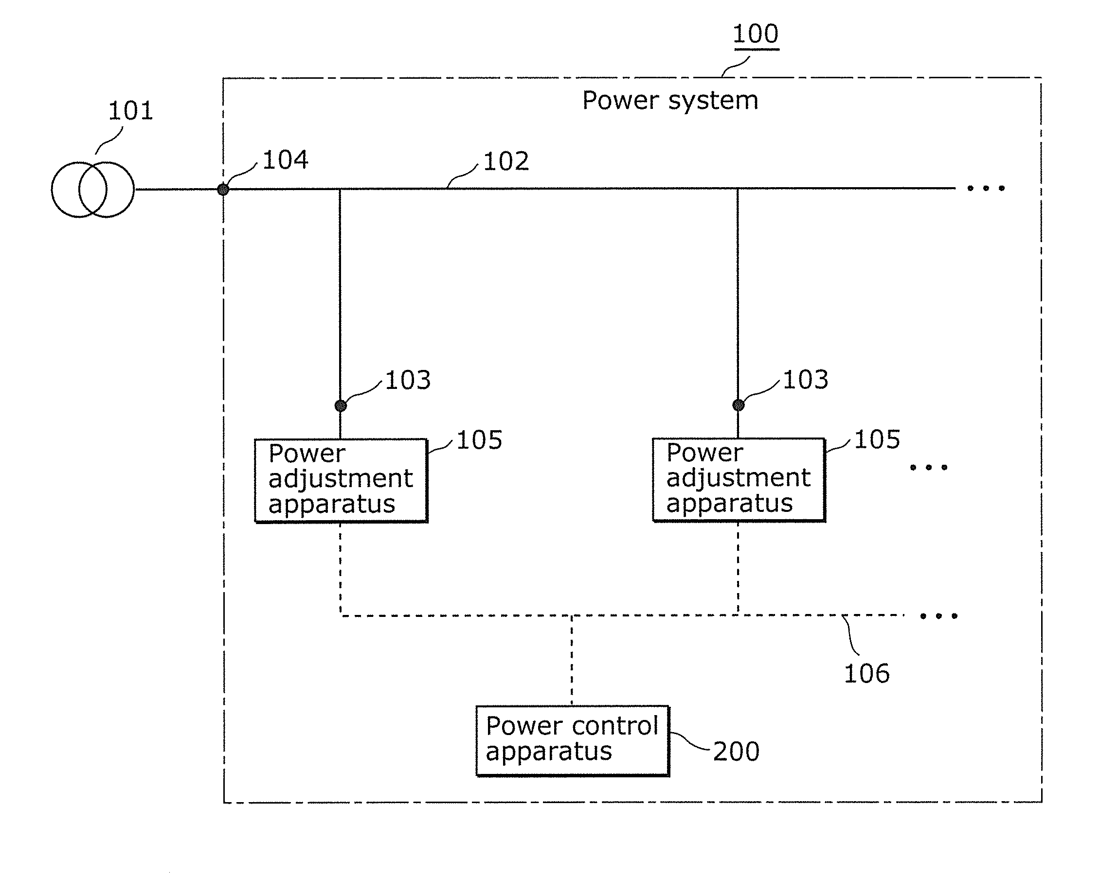
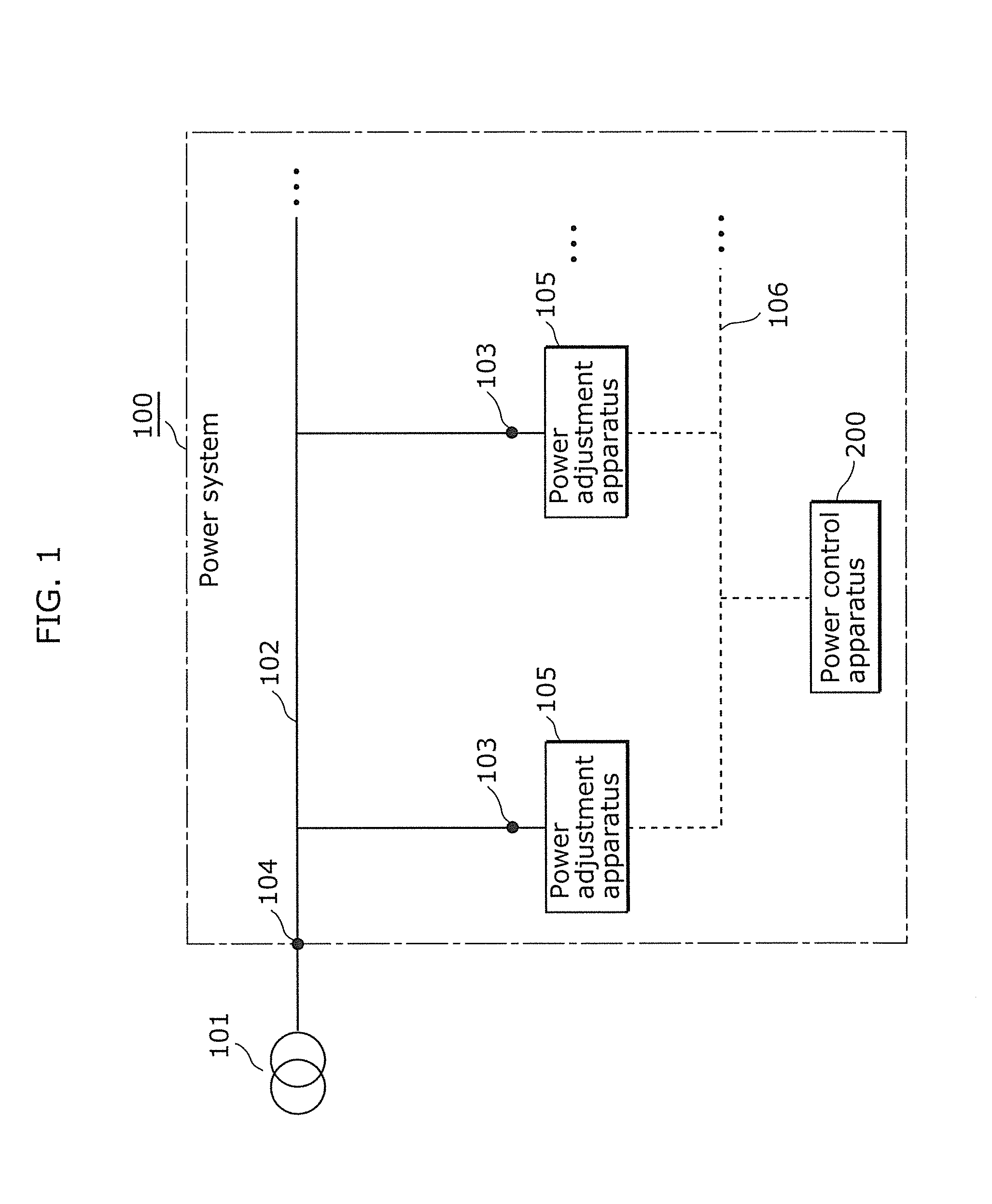
[0060]FIG. 1 is a conceptual diagram illustrating a power system in which a power control apparatus according to Embodiment 1 is provided. As FIG. 1 illustrates, a power system 100 includes a power line 102, voltage measuring points 103, a power flow measuring point 104, power adjustment apparatuses 105, a communication line 106, and a power control apparatus 200. This power system 100 is interconnected with a substation 101 as an upper power system via the power flow measuring point 104.

[0061]The power line 102 supplies power from the substation 101 to each of the power adjustment apparatuses 105.

[0062]The voltage measuring point 103 is, for example, a power reception point at which the power adjustment apparatus 105 and the power system 100 are interconnected and at which the power adjustment apparatus 105 can obtain a voltage value. It should be noted that a method for detecting a voltage value at the voltage measuring point 103 is not limited to one method. In the present embodi...

embodiment 2

[0112]FIG. 7 is a block diagram illustrating a functional configuration of a power control apparatus according to Embodiment 2. FIG. 8 is a flowchart illustrating the procedure of power control by the power control apparatus in FIG. 7. It should be noted that in the present embodiment, the same elements as Embodiment 1 are given the same reference signs and the explanation will be omitted.

[0113]As FIG. 7 illustrates, a power control apparatus 200A in the present embodiment further includes a control accuracy setting unit 206. This control accuracy setting unit 206 sets a relationship in accuracy level between the accuracy of power flow control by the power flow control unit 203 and the accuracy of voltage control by the voltage control unit 204. In the power flow control, a first deviation value is controlled which represents deviation of a power flow value at the power flow measuring point 104 from a predetermined target value. Meanwhile, in the voltage control, a second deviation ...


PUM


Abstract

A power control apparatus includes: a first obtainment unit which obtains a power flow value at a power flow measuring point and a voltage value at a voltage measuring point provided; a power flow control unit which calculates a first power change value, to cause the power flow value to approach a predetermined target value; a voltage control unit calculates a voltage value at the voltage measuring point when the first power has been changed by the first power change value, and sets a second power change value, based on whether or not the voltage value falls within a predetermined voltage range; and a notification unit which notifies the power adjustment apparatus of a command value for causing the power adjustment apparatus to input or output the first power changed by the first power change value and the second power changed by the second power change value.

Description

TECHNICAL FIELD[0001]The present invention relates to power control apparatuses, power control methods, and power control programs and, in particular, to a power control apparatus, a power control method, and a power control program for controlling a power flow value and a voltage value in a power system interconnected with power adjustment apparatuses such as dispersed power sources.BACKGROUND ART[0002]In recent years, dispersed power sources such as a photovoltaic power generating system have been introduced in, for example, households and office buildings. Such dispersed power sources are interconnected with power systems. Of power generated by the dispersed power sources, power which has not been consumed by loads in the households and office buildings flows back to the power system as surplus power. The surplus power is then sold to a power company. However, if many dispersed power sources are interconnected with a power system, abrupt changes may occur in power flow and voltag...

Claims


Application Information

Patent Timeline
IPC IPC(8): H02J3/18
CPCH02J3/18H02J3/46H02J3/06Y04S40/12Y02E40/30G05F5/00G05F1/00H02J2203/20H02J13/00006H02J13/00034Y02B90/20Y02E60/00Y04S40/20Y04S10/22Y02E40/70H02J3/0012H02M1/32Y04S10/52
Inventor WATANABE, KENICHI
Owner PANASONIC CORP
Why Eureka
Try Eureka