
Calibration method of line structured light three-dimensional measurement system

A technology of three-dimensional measurement and line-structured light, which is applied in the direction of measuring devices, optical devices, instruments, etc., can solve the problems of small application range, large amount of calculation, and low efficiency, and achieve high calibration efficiency, low hardware requirements, and simplified calculations volume effect

Pending Publication Date: 2021-12-31
XI AN ZHISENSOR TECH CO LTD
View PDF1 Cites 0 Cited by
  • Summary
  • Abstract
  • Description
  • Claims
  • Application Information

AI Technical Summary

Problems solved by technology

[0005] Aiming at the problems of small application range, high cost, large amount of calculation, and low efficiency existing in the calibration method of the existing line structured light three-dimensional measurement system, and at the same time eliminating the influence of lens distortion on the measurement accuracy, the present invention proposes a line structured light three-dimensional measurement system. Calibration method, this method only uses unidirectional fringe pattern for calibration, so it is not only suitable for conventional systems with two-dimensional projection capabilities, but also can perform high-precision calibration for systems that only support unidirectional fringe projection

Method used


Image

  • Calibration method of line structured light three-dimensional measurement system
  • Calibration method of line structured light three-dimensional measurement system
  • Calibration method of line structured light three-dimensional measurement system

Examples


Embodiment Construction

[0044] Below in conjunction with accompanying drawing and embodiment the present invention is described in detail

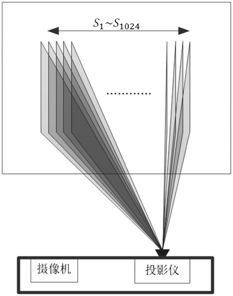
[0045] Such as figure 1 As shown, in this embodiment, the line-structured light three-dimensional measurement system to be calibrated is mainly composed of a camera and a projector. Projector capable of projecting 1024 vertical stripes 1 ~S 1024 , a group of structured light coding patterns are projected in turn to form a coded structured light sequence; the resolution of the camera is 640*480.

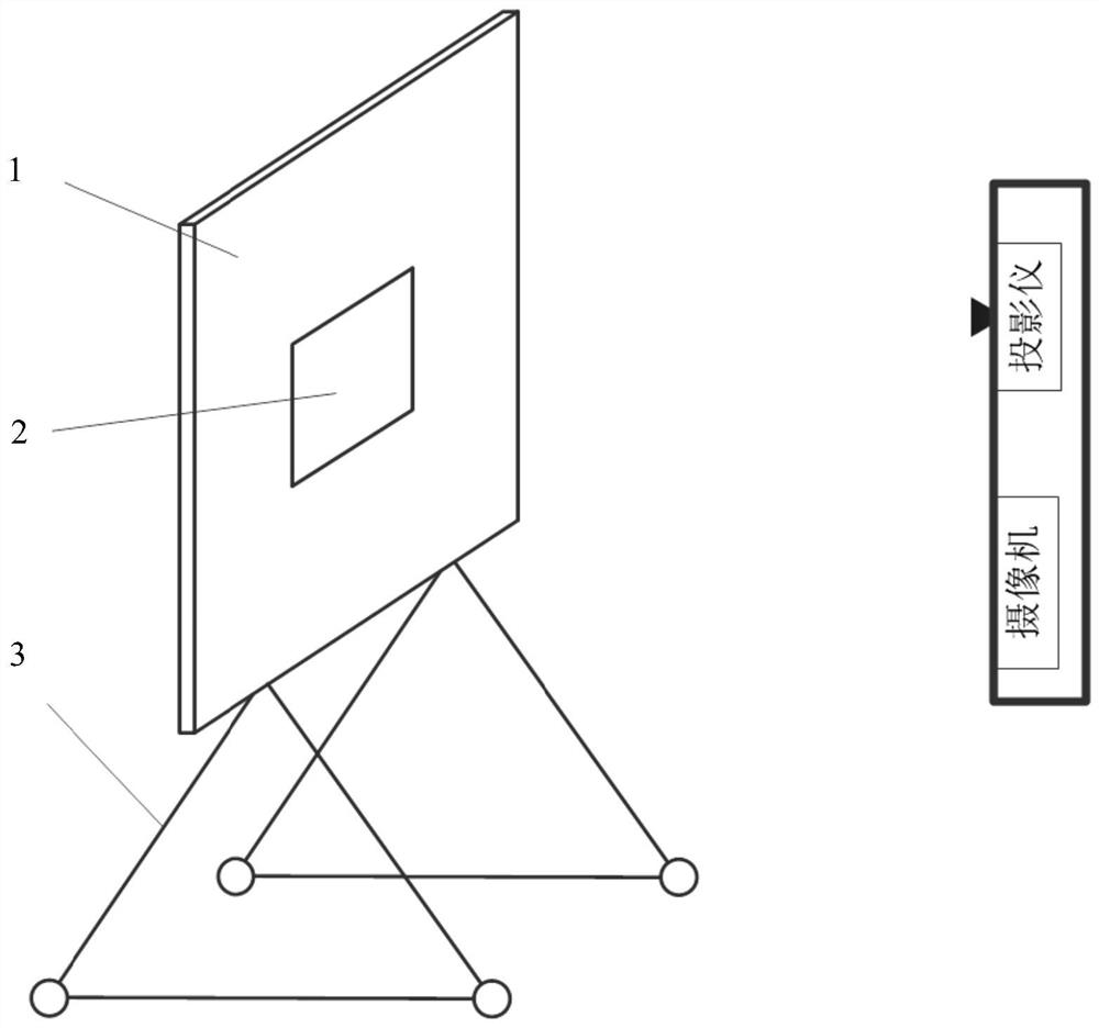
[0046] Use a plane calibration board to realize the calibration of the line structured light three-dimensional measurement system. The plane calibration board should be as flat as possible to reduce calibration errors; the area should be large enough to enable all structured light stripes to be imaged on the board at the same time; The flat calibration plate 1 such as figure 2 As shown, it is installed on the movable support 3 and can be moved in any direction when ...


PUM

PropertyMeasurementUnit
Thicknessaaaaaaaaaa

Abstract

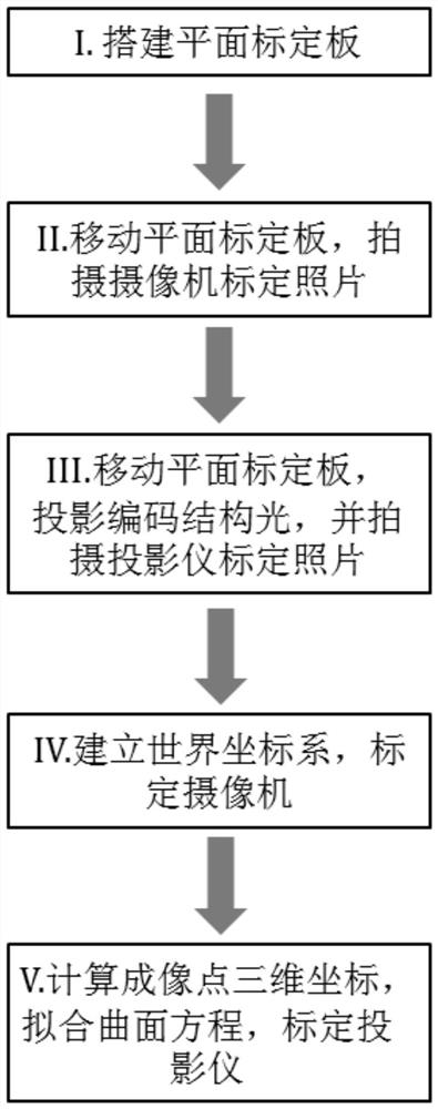
The invention belongs to the field of optical three-dimensional measurement, particularly relates to a calibration method of a line structured light three-dimensional measurement system, aims to solve the problems of small application range, high cost, large calculation amount, low efficiency and the like of the existing calibration method of the line structured light three-dimensional measurement system, and eliminates the influence of lens distortion on measurement precision. The method mainly comprises the following steps: building a plane calibration plate required by calibration; moving the plane calibration plate or the linear structured light three-dimensional measurement system, and taking a picture; moving the plane calibration plate or the linear structured light three-dimensional measurement system, projecting coding structured light, and taking a picture; calibrating the camera, and obtaining a plane equation of the plane calibration plate in a camera image plane coordinate system; and calculating three-dimensional coordinates of imaging points, fitting a curved surface equation, and calibrating the projector. According to the curved surface equation, the calculated amount of curved surface fitting is simplified, the overfitting problem which is extremely prone to occurring in a conventional second-order curved surface equation is avoided, and compared with the conventional second-order curved surface equation, the spatial model of the structured light curved surface can be described more accurately.

Description

technical field [0001] The invention belongs to the field of optical three-dimensional measurement, and in particular relates to a calibration method for a line structured light three-dimensional measurement system. The method is based on an optimized second-order surface equation and realizes high-precision calibration of the line structured light three-dimensional measurement system. Background technique [0002] Line structured light 3D measurement technology is one of the most widely used 3D measurement technologies at present. It has the advantages of fast speed, high precision and no damage to the measured object. It has been applied to quality inspection, medical imaging, face recognition, reverse engineering, Archeology and many other fields. The line structured light 3D measurement system is mainly composed of a camera and a line stripe projector. During the measurement, the line stripe projector projects a set of structured light coding patterns, which are cast on...

Claims


Application Information

Patent Timeline
IPC IPC(8): G01B11/25
CPCG01B11/254
Inventor 杨迪乔大勇夏长锋
Owner XI AN ZHISENSOR TECH CO LTD
Learn More