Image display apparatus, control method of image display apparatus, light source apparatus, and control method of light source apparatus

Inactive Publication Date: 2015-05-07
CANON KK
View PDF11 Cites 2 Cited by
  • Summary
  • Abstract
  • Description
  • Claims
  • Application Information

AI Technical Summary

Benefits of technology

The present invention describes a technique that allows for quickly and accurately getting the light levels of all light sources. This means that light levels can be measured quickly and with high precision.

Problems solved by technology

However, light from a light source leaks to another divided region.
Therefore, according to the technique disclosed in WO 2008 / 029548, a detection value obtained by a light sensor undesirably contains a large detection error.

Method used


Image

  • Image display apparatus, control method of image display apparatus, light  source apparatus, and control method of light source apparatus
  • Image display apparatus, control method of image display apparatus, light  source apparatus, and control method of light source apparatus
  • Image display apparatus, control method of image display apparatus, light  source apparatus, and control method of light source apparatus

Examples


embodiment 1

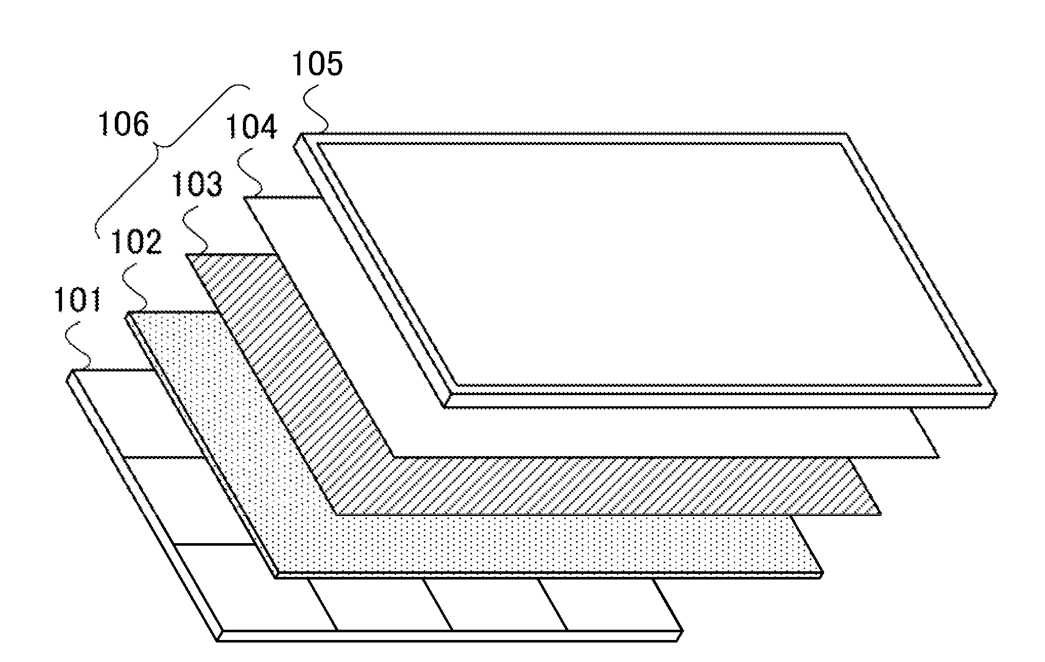
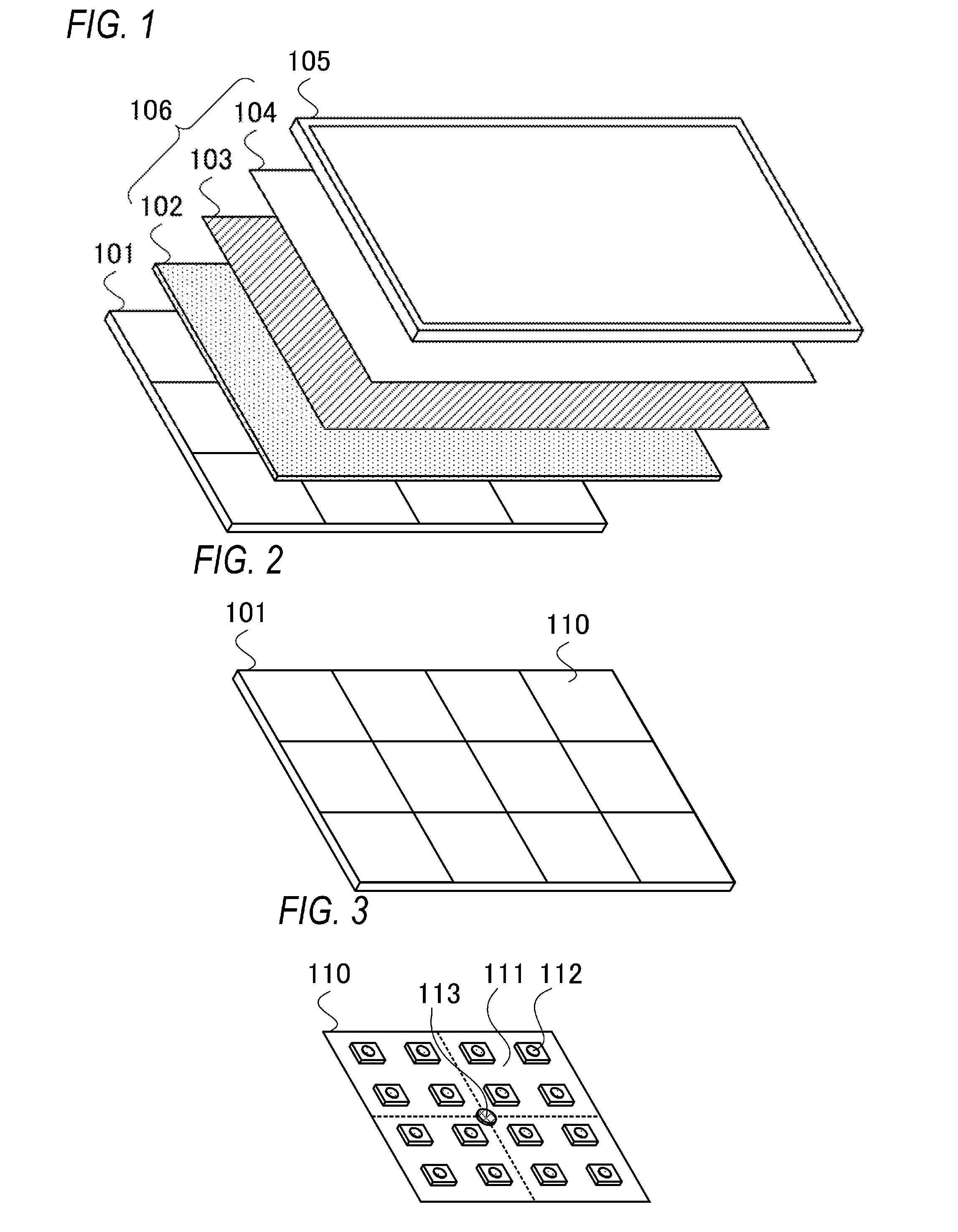
[0076]Alight source apparatus and a control method of the light source apparatus according to Embodiment 1 of the present invention are described below.

[0077]In the following description, an example in which the light source apparatus according to the present embodiment is used in an image display apparatus that displays an image on a screen by modulating light from the light source apparatus is described. However, the light source apparatus according to the present embodiment is not limited to this. The light source apparatus according to the present embodiment may be, for example, an illumination apparatus such as a street lamp or interior illumination.

[0078]In the following description, an example in which an image display apparatus according to the present embodiment is a transmissive liquid crystal display apparatus is described. However, the image display apparatus according to the present embodiment is not limited to this. The image display apparatus according to the present ...

embodiment 2

[0170]A light source apparatus and a control method of the light source apparatus according to Embodiment 2 of the present invention are described below.

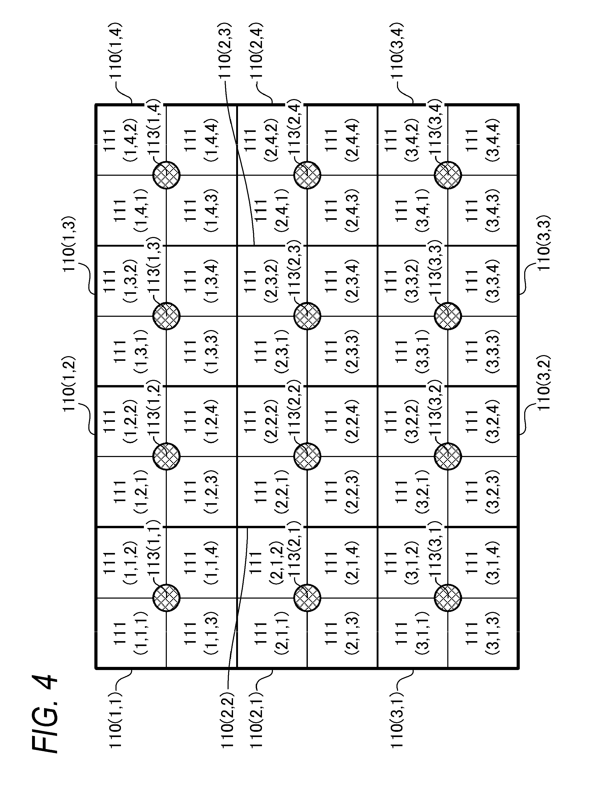
[0171]Embodiment 1 has described an example in which two light sources are concurrently turned on in the light emission adjusting processing. The present embodiment describes an example in which more than two light sources are concurrently turned on in the light emission adjusting processing. Specifically, the present embodiment describes an example in which three light sources are concurrently turned on in the light emission adjusting processing. That is, the present embodiment describes an example in which N is 3.

[0172]It should be noted that, in the following description, a configuration and processing that are different from those in Embodiment 1 are described in detail, and description of an identical configuration and identical processing to those in Embodiment 1 is omitted.

[0173]A configuration of an image display apparatus a...


PUM


Abstract

An image display apparatus includes N detecting units, a light emitting unit having n light sources for each of the detecting units, a control unit configured to control light emission of the light sources, a storage unit configured to store, for each combination of the light source and a detecting unit that does not correspond to the light source, a degree of influence of light from the light source on a detection value, and an acquiring unit configured to acquire a light value of the light source on the basis of N detection values that are obtained in the state where the N light sources are being turned on and the degrees, wherein the control unit performing processing of turning on the N light sources n times to acquire light values of N×n light sources.

Description

BACKGROUND OF THE INVENTION[0001]1. Field of the Invention[0002]The present invention relates to an image display apparatus, a control method of an image display apparatus, a light source apparatus, and a control method of a light source apparatus.[0003]2. Description of the Related Art[0004]A liquid crystal display apparatus that is capable of displaying a color image generally includes a liquid crystal panel having color filters and a backlight apparatus that irradiates the back face of the liquid crystal panel with white light.[0005]Conventionally, a fluorescent lamp such as a cold cathode fluorescent lamp (CCFL) is mainly used as a light emitting element of a backlight apparatus. However, in recent years, a light emitting diode (LED), which is excellent in terms of electric power consumption, lifetime, color reproducibility, and load on the environment is increasingly used as a light emitting element of a backlight apparatus.[0006]A backlight apparatus that has LEDs as light emi...

Claims


Application Information

Patent Timeline
IPC IPC(8): G09G3/34G09G3/36H05B37/02
CPCG09G3/3406H05B37/0218G09G2360/141G09G2320/0626G09G2330/021G09G3/36G09G3/3426H05B47/11Y02B20/40
Inventor KURITA, MASANAO
Owner CANON KK
Why Eureka
Try Eureka