
Radio repeater apparatus and system, and operating method thereof

a repeater and radio technology, applied in the field of radio repeater apparatus and system, and an operating method thereof, can solve the problems of degrading the quality of the signals received by the terminal, the inability to obtain the installation and the inability to obtain the operation effect of the radio repeater system

Active Publication Date: 2015-05-07
AIRPOINT
View PDF3 Cites 15 Cited by
  • Summary
  • Abstract
  • Description
  • Claims
  • Application Information

AI Technical Summary

Benefits of technology

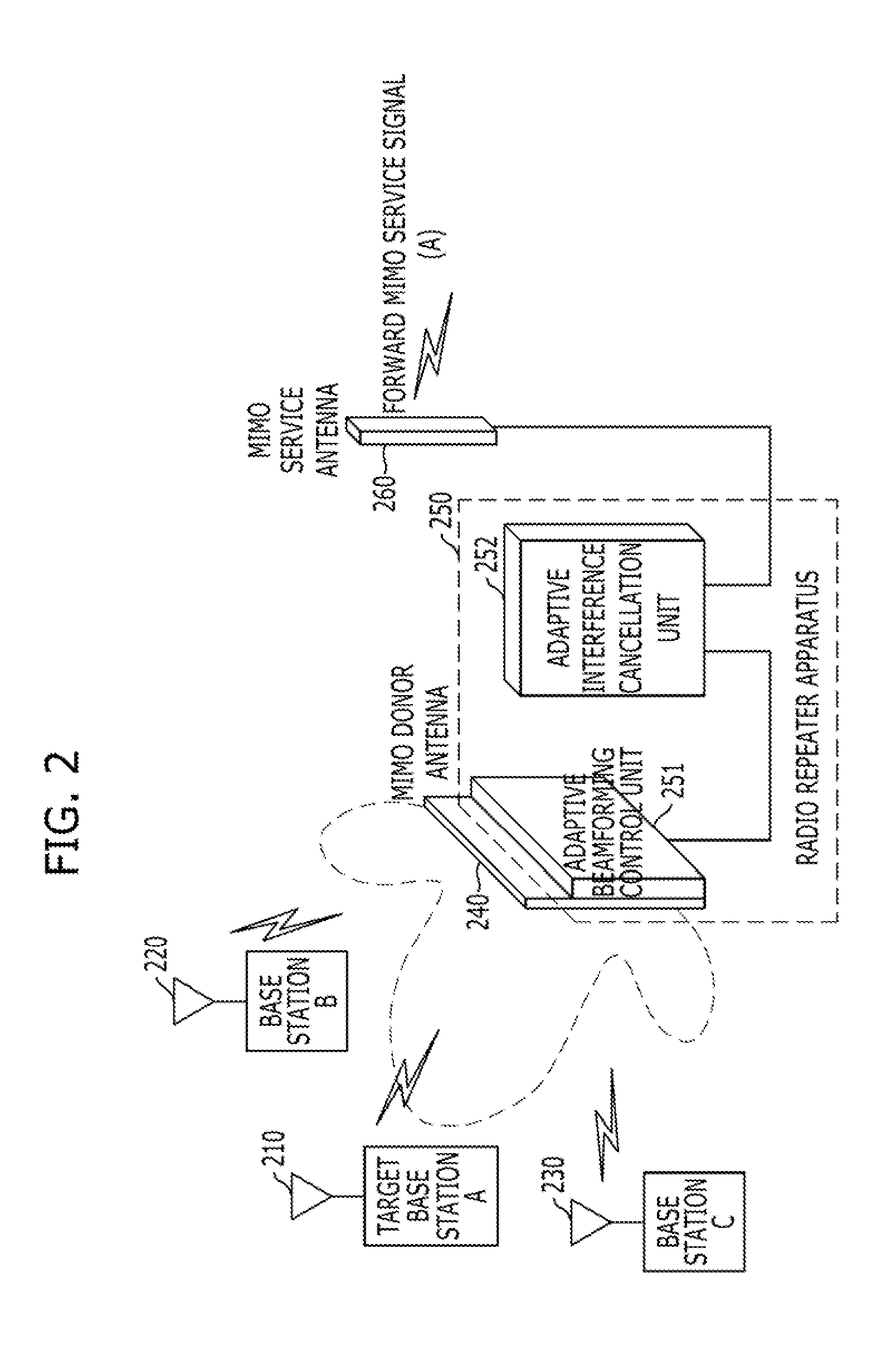
The present invention provides a radio repeater system and method that can adaptively cancel feedback interference signals and operate adaptively in change of radio channel environment. The system includes a multiple input multiple output donor antenna, beamforming control unit, interference signal cancellation unit, and MIMO service antenna. The method includes receiving MIMO signals, controlling beamforming, estimating and analyzing feedback interference signals, and canceling the signals. The system and method improve signal quality and stability of the transmission and reception of MIMO signals.

Problems solved by technology

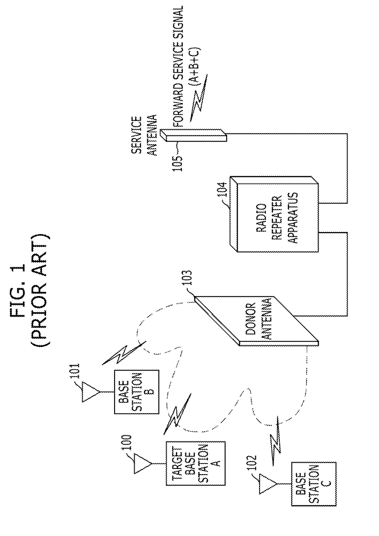
The signals received from the other base stations serve as interference signals which may cause radio interference when the same radio resource is used, and degrade the quality of the signals received by the terminals due to a frequency error between the respective base stations.
In this case, since the signal quality of the service area is degraded, the installation effect of the radio repeater system may not be obtained.
In this case, the operation effect of the radio repeater system may not be obtained.
In this case, since the gain of the radio repeater system cannot be increased to inevitably reduce the coverage of the service area, the efficiency of the radio repeater system may decrease.
Therefore, the conventional radio repeater system has disadvantages in that the repeating quality of downlink signals is degraded, the frequency use efficiency is decreased, and the stability of repeated signals is reduced.

Method used


Image

  • Radio repeater apparatus and system, and operating method thereof
  • Radio repeater apparatus and system, and operating method thereof
  • Radio repeater apparatus and system, and operating method thereof

Examples


Embodiment Construction

[0027]Exemplary embodiments of the present invention will be described below in more detail with reference to the accompanying drawings. The present invention may, however, be embodied in different forms and should not be constructed as limited to the embodiments set forth herein. Rather, these embodiments are provided so that this disclosure will be thorough and complete, and will fully convey the scope of the present invention to those skilled in the art.

[0028]In this disclosure below, when one part is referred to as being ‘connected’ to another part, it should be understood that the former can be ‘directly connected’ to the latter, or ‘electrically connected’ to the latter via an intervening part. Furthermore, when it is described that one comprises (or includes or has) some elements, it should be understood that it may comprise (or include or has) only those elements, or it may comprise (or include or have) other elements as well as those elements if there is no specific limitat...


PUM


Abstract

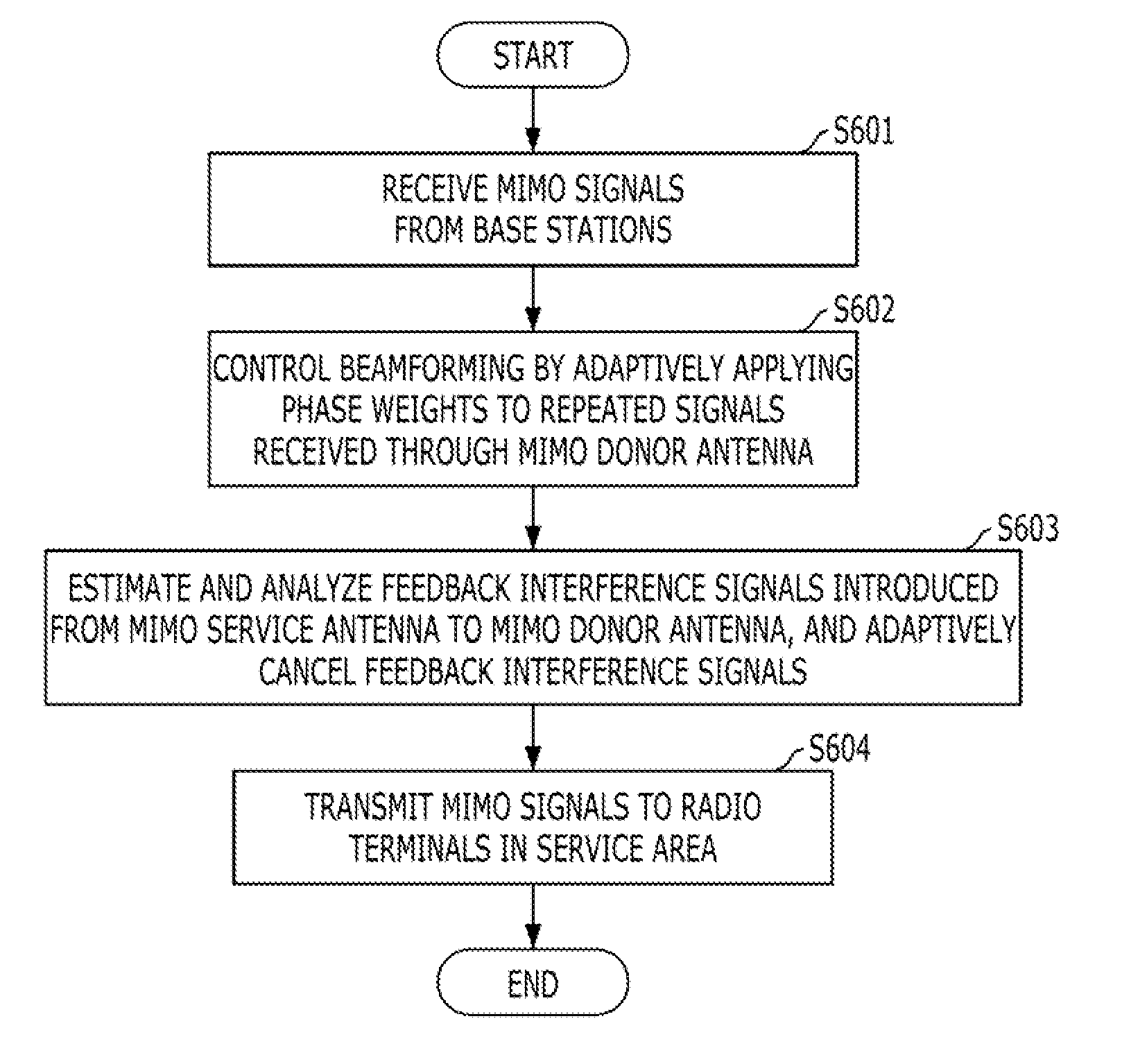
A radio repeater system may include: a multiple input multiple output (MIMO) donor antenna configured to transmit / receive MIMO signals to / from base stations; a beamforming control unit configured to control beamforming by adaptively applying a phase weight to the repeated signals received from the MIMO donor antenna; an interference signal cancellation unit configured to estimate and analyze feedback interference signals introduced from a MIMO service antenna to the MIMO donor antenna and adaptively cancel the feedback interference signals; and the MIMO service antenna configured to transmit / receive MIMO signals to / from radio terminals in a service area.

Description

CROSS-REFERENCE TO RELATED APPLICATIONS[0001]The present application claims priority of Korean Patent Application No. 10-2013-0134167, filed on Nov. 6, 2013, which is incorporated herein by reference in its entirety.BACKGROUND OF THE INVENTION[0002]1. Field of the Invention[0003]Exemplary embodiments of the present invention relate to a radio repeater apparatus and system, and an operating method thereof; and, more particularly, to a radio repeater apparatus and system, which is capable of strengthening a repeating target base station signal (target base station signal) among various base station signals which are mixed and received, and suppressing the other base station signals to reduce interference between the base station signals, in order to improve the repeating quality of downlink signals, and an operating method thereof.[0004]2. Description of Related Art[0005]In general, a radio repeater system is a system which receives and amplifies a downlink signal transmitted from a r...

Claims


Application Information

Patent Timeline
IPC IPC(8): H04B7/155H04B7/04
CPCH04B7/0413H04B7/15564H04B7/10H04B7/005H04B7/02H04B7/14
Inventor AHN, BYUNGYANG
Owner AIRPOINT
Learn More