
Propeller sound field modification systems and methods

Active Publication Date: 2015-05-07
KCF TECHNOLOGIES
View PDF2 Cites 24 Cited by
  • Summary
  • Abstract
  • Description
  • Claims
  • Application Information

AI Technical Summary

Benefits of technology

The patent describes a system that modifies the sound of an aircraft's propeller system using an acoustic resonator. The resonator is excited by the flow of air from the blade tips and directs the acoustic energy to modify the sound field in a desired direction. The system takes into account the speed, orientation of the aircraft, and weather condition to determine the best way to modify the acoustic profile. The technical effect is the reduction of noise and improved performance of the aircraft's propeller system.

Problems solved by technology

Tonal noise results from propeller blade interactions with time-invariant flow distortions.
When spectrally dominant, blade tones are of primary concern in noise control applications due to their particular annoyance.
The noise problem is particularly acute for surveillance aircraft and drones that must avoid detection or creating a nuisance near populated areas.
Several conventional techniques have been used to reduce propeller noise, but they all tend to reduce the efficiency of the propeller.
Few passive approaches have demonstrated the ability to reduce blade tone noise locally in the blade region with minimal impact on fan efficiency.
However, difficulty in tuning the response of these interactions often limits their usefulness.
These approaches have proven effective in a laboratory setting, but are generally prohibitively expensive and potentially unreliable in most actual axial fan applications.
A key barrier to implementing sound cancellation methods in aircraft is the added weight.
For previous systems, the weight penalty has generally been too high for the acoustic performance gains.

Method used


Image

  • Propeller sound field modification systems and methods
  • Propeller sound field modification systems and methods
  • Propeller sound field modification systems and methods

Examples


Embodiment Construction

[0025]Reference will now be made in detail to specific embodiments or features, examples of which are illustrated in the accompanying drawings. Generally, corresponding or similar reference numbers will be used, when possible, throughout the drawings to refer to the same or corresponding parts.

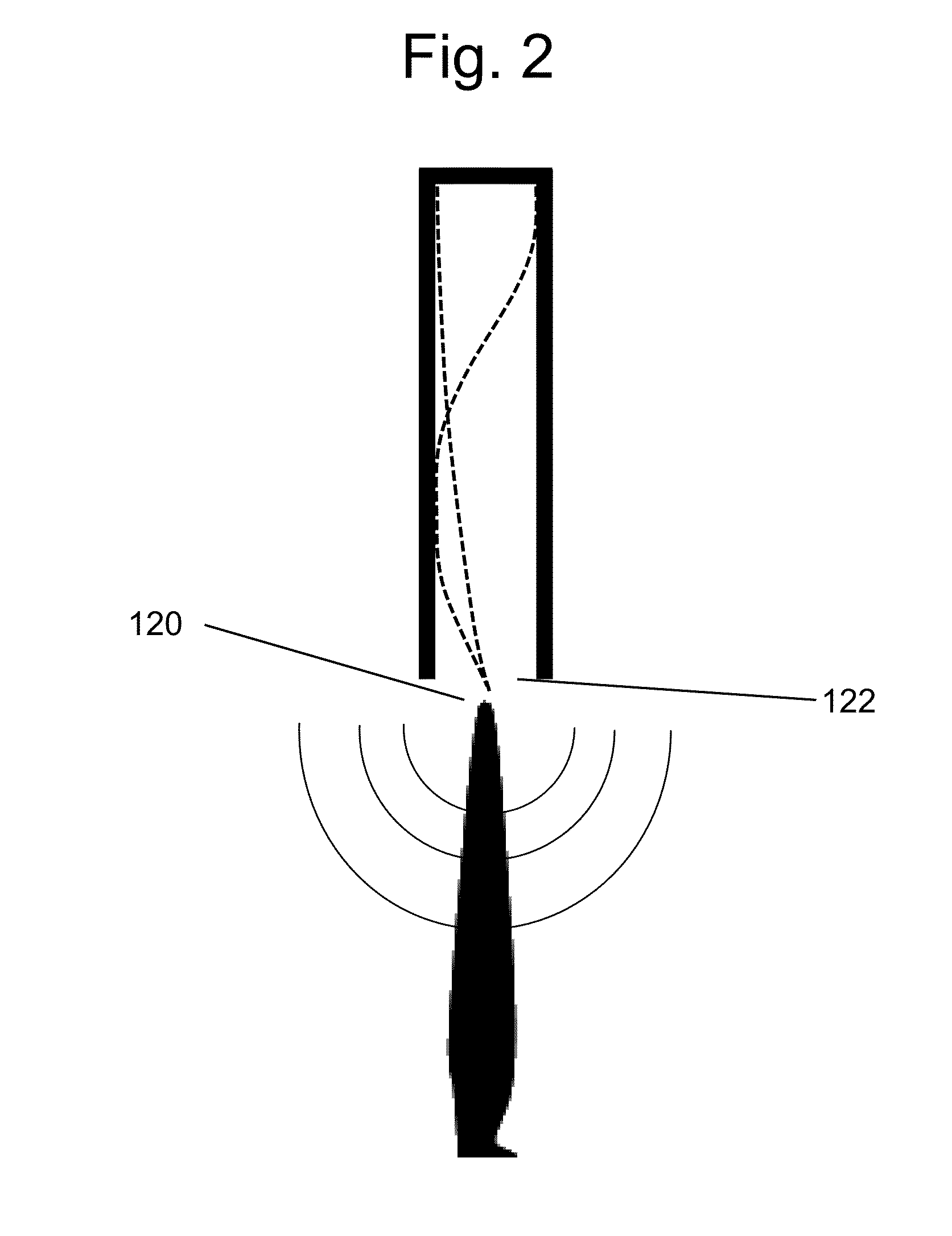
[0026]The present invention provides an acoustic resonator configuration for use with or as part of a propeller system so as to provide modification of propeller fan noise propagation and / or shaping of a propeller sound field. In some aspects, the acoustic resonator may cancel the entirety or a substantial portion of the tonal component of noise from the propeller in one or more directions.

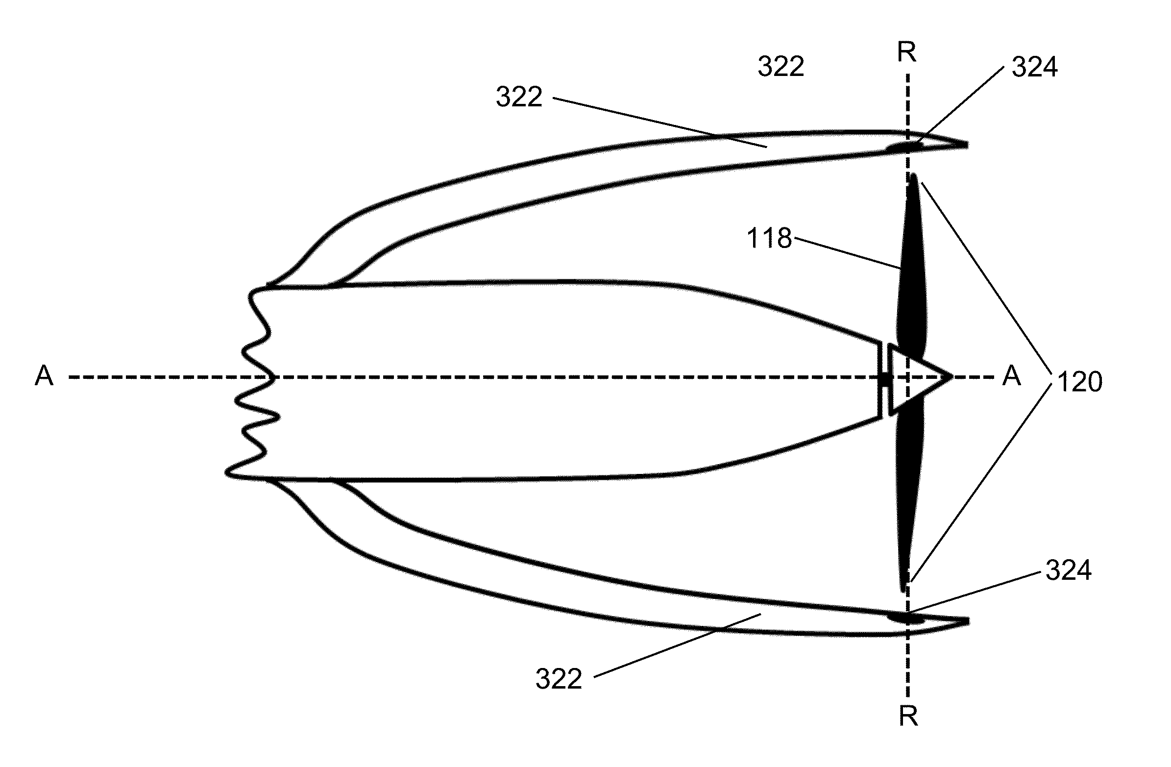
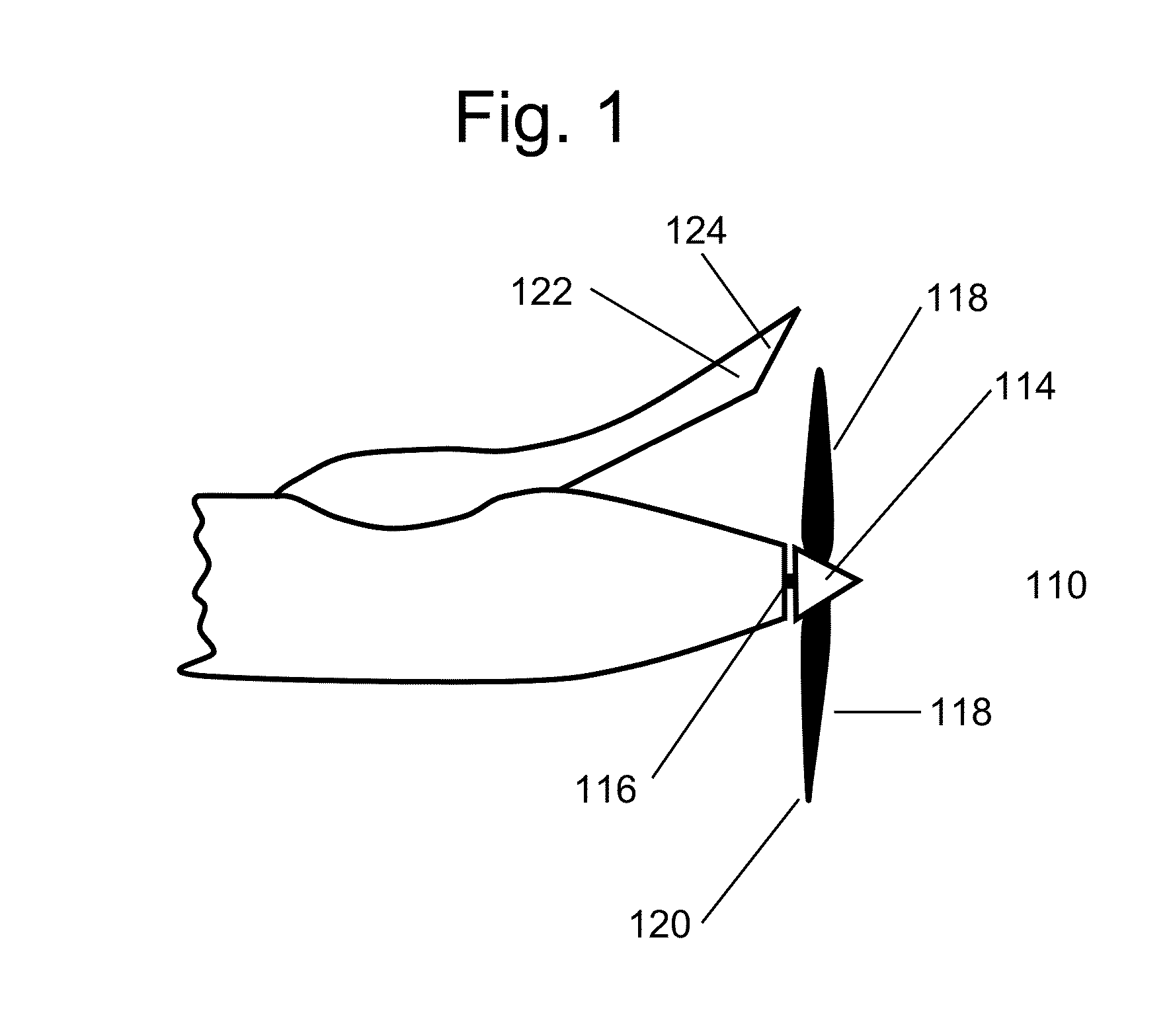
[0027]Referring to FIG. 1, a propeller system 110 according to an embodiment of the present disclosure includes a rotor 114 rotatable about a rotor axis A. As shown, the rotor 114 has a central hub 116 and a plurality of rotor blades 118 extending outwardly from the hub 116 to tips 120. The rotor blades 118 ...


PUM


Abstract

A propeller system for an aircraft includes an assembly for modifying a sound field of the propeller system. The propeller system includes a rotor supported for rotation about a rotor axis. The rotor has a central hub and a plurality of blades each extending outwardly from the hub to a tip. The rotor and blades are operable to propel an aircraft to travel in a direction. The rotor blades define a rotor plane perpendicular to the rotor axis. The blade tips define a circumferential rotational path as the blades are rotated by the rotor. The propeller system includes an acoustic resonator or multiple resonators having openings disposed within a distance to the propeller blade tip that is small compared to the wavelength of the propeller's fundamental blade tone and proximate to the rotor plane. The resonators are excited by tip flow of the blade as it passes the opening. The acoustic resonators are configured and positioned so as to direct acoustic energy to modify the sound field of the propeller system at blade pass or higher harmonic frequency tones in a desired direction relative to the aircraft.

Description

CROSS-REFERENCE TO RELATED APPLICATION[0001]This application claims the benefit of U.S. Provisional Patent Application No. 61 / 802,205, having a filing date of 15 Mar. 2013, which is hereby incorporated by reference.GOVERNMENT LICENSE RIGHTS[0002]This invention was made with United States government support under U.S. Navy SBIR Award No. N68936-11-C-0017. The government has certain rights in this invention.TECHNICAL FIELD[0003]The present disclosure relates generally to propeller sound field modification and, more specifically, to systems and methods for modifying the sound field of an aircraft propeller.BACKGROUND[0004]It is common knowledge that propeller systems, for example, aircraft propeller systems, pushers, tractors, and tail rotors, generate a noise signature. It is generally desirable to reduce the noise signature of propellers. As noted in U.S. Pat. No. 7,992,674, the disclosure of which is incorporated herein, noise generated by propeller systems has both broadband and to...

Claims


Application Information

Patent Timeline
IPC IPC(8): B64C1/40B64C11/00
CPCB64C1/40B64C2220/00F05D2260/96B64C11/001
Inventor KOOPMANN, GARY H.GRISSOM, MICHAEL D.
Owner KCF TECHNOLOGIES
Learn More