Apparatus and method for mounting electronic component

a technology for mounting apparatuses and electronic components, applied in metal working apparatuses, printed circuit manufacture, manufacturing tools, etc., can solve the problems of insufficient progress in the introduction of electronic component mounting apparatuses exclusively used for variant components in view of working costs, and the size or the form of electronic components can be increased, and the working cost can be extremely improved

Active Publication Date: 2015-05-14
PANASONIC INTELLECTUAL PROPERTY MANAGEMENT CO LTD
View PDF2 Cites 13 Cited by
  • Summary
  • Abstract
  • Description
  • Claims
  • Application Information

AI Technical Summary

Benefits of technology

[0010]According to the present invention, the general-purpose property for the size or the form of the electronic component can be increased and the working cost can be extremely improved.

Problems solved by technology

However, since the chuck member of the usual electronic component mounting apparatus is extremely low in general-purpose property for a difference of size or form of the component, kinds of electronic components which can be met by the single chuck member are restricted.
Accordingly, in a mounting line which treats the variant components, a problem arises that an introduction of the electronic component mounting apparatus exclusively used for the variant components does not progress in view of working cost and an operation in the mounting line yet depends on a human power.

Method used


Image

  • Apparatus  and method for mounting electronic component
  • Apparatus  and method for mounting electronic component
  • Apparatus  and method for mounting electronic component

Examples


Embodiment Construction

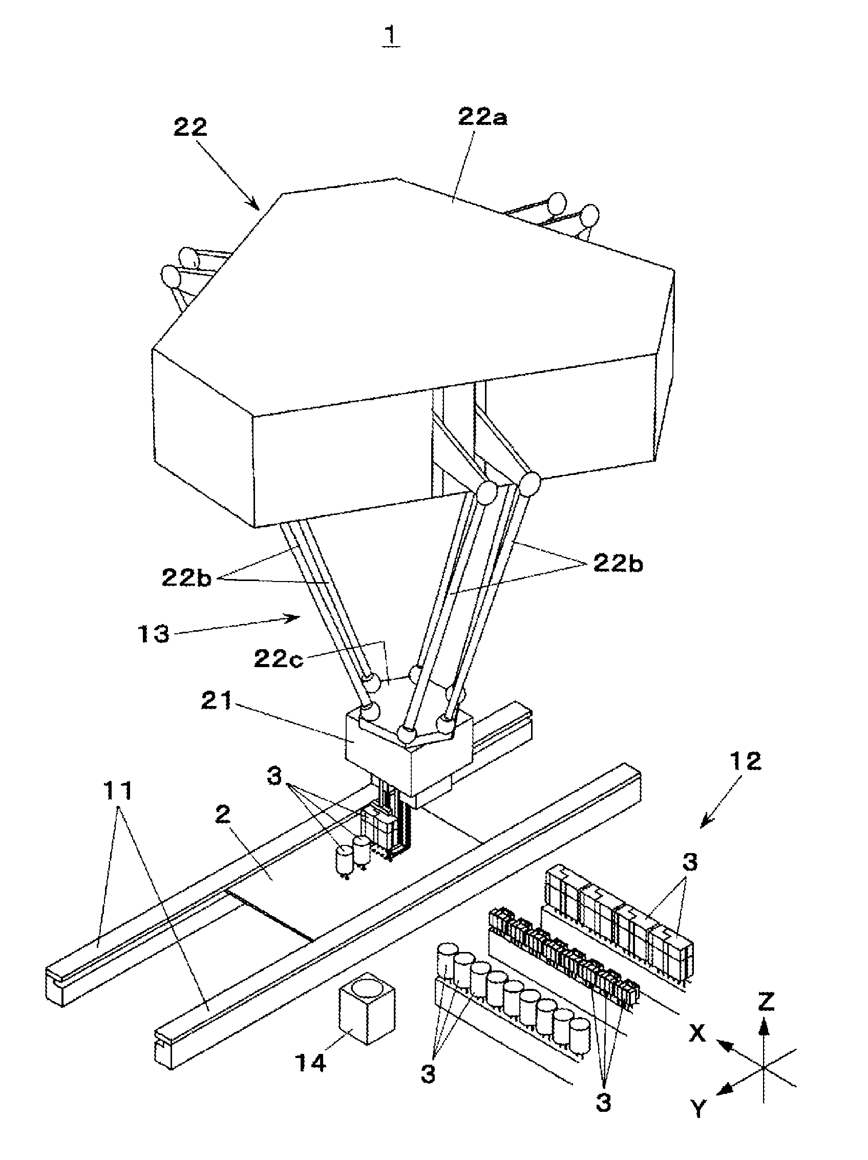
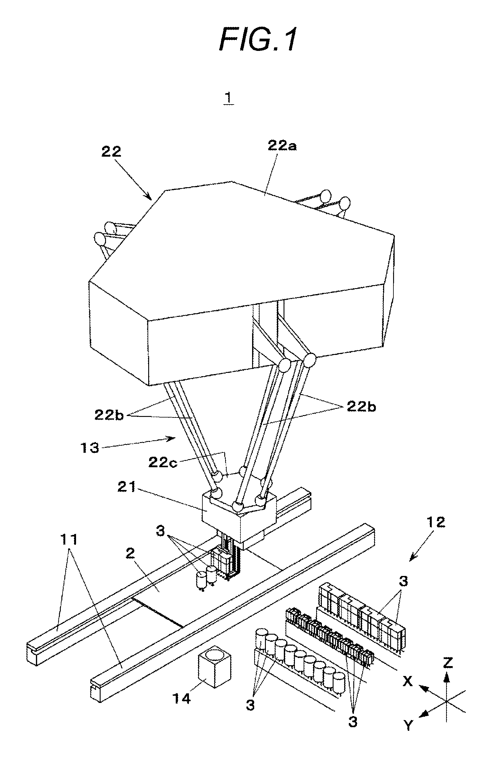
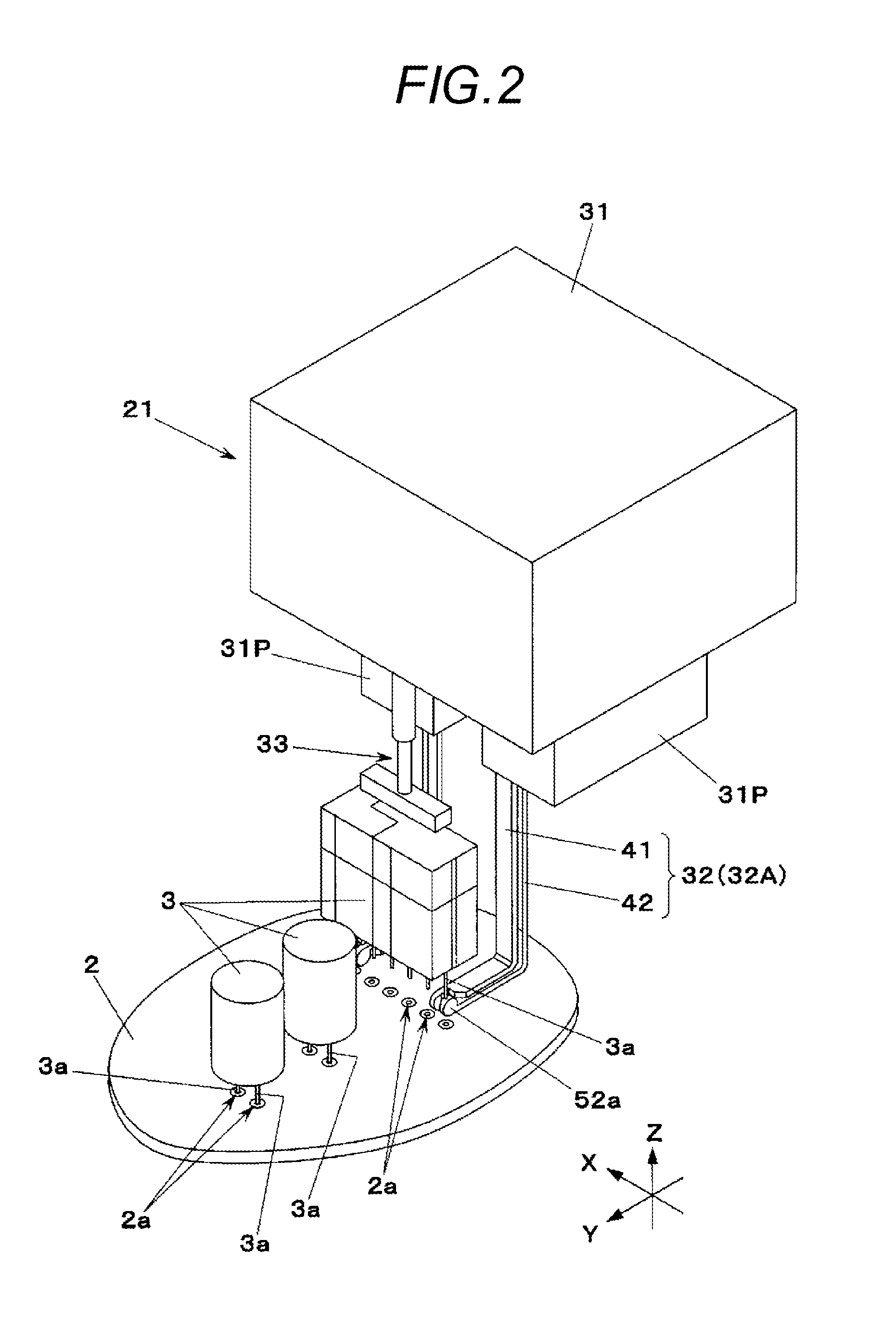
[0021]Now, referring to the drawings, an exemplary embodiment of the present invention will be described below. An electronic component mounting apparatus 1 shown in FIG. 1 is an apparatus which mounts an electronic component 3 on a board 2. The electronic component mounting apparatus 1 includes a board carrying conveyor 11 which conveys the board 2 and positions the board 2 in a prescribed working position, a component feeder 12 which feeds various kinds of electronic components 3, a component mounting mechanism 13 provided in an upper part of the board carrying conveyor 11 and a recognition camera 14 installed with its image pick-up visual field directed upward. As shown in FIG. 2, the electronic component 3 has a plurality of board insert type leads 3a which are extended downward. On the board 2, a plurality of lead insert holes 2a are provided so as to meet arrangements of the leads 3a of the electronic components 3 respectively.

[0022]In FIG. 1, the component mounting mechanism ...


PUM

PropertyMeasurementUnit
sizeaaaaaaaaaa
sizesaaaaaaaaaa
anglesaaaaaaaaaa

Abstract

Provided is an apparatus for mounting an electronic component having a plurality of board insert type leads on a board. The apparatus includes a mounting head having a first chuck unit which chucks one of the plurality of leads of the electronic component, a second chuck unit which chucks another one of the plurality of leads and a position adjusting unit which changes relative positions of the first chuck unit and the second chuck unit to hold the electronic component, and a mounting head moving unit which moves the mounting head to insert the leads of the electronic component held by the mounting head respectively into lead insert holes provided in the board.

Description

CROSS REFERENCE TO RELATED APPLICATIONS[0001]The present application is based on and claims the benefit of Japanese patent application No. 2013-234698 filed on Nov. 13, 2013, the contents of which are incorporated by reference in its entiretyBACKGROUND OF THE INVENTION[0002]1. Field of the Invention[0003]The present invention relates to an apparatus and a method for mounting an electronic component having a plurality of board insert type leads on a board.[0004]2. Description of the Related Art[0005]An electronic component mounting apparatus which mounts an electronic component having a plurality of board insert type leads on a board is usually formed to move a mounting head which grips a main body part (a body part) of the electronic component by a chuck member so that the leads provided in the electronic component are respectively inserted into lead insert holes provided in the board (for instance, JP-A-2000-261194).SUMMARY OF THE INVENTION[0006]However, since the chuck member of t...

Claims


Application Information

Patent Timeline
Patent Type & Authority Applications(United States)
IPC IPC(8): H05K13/04H05K3/30
CPCH05K13/0413H05K2203/0147H05K2203/166H05K3/306H05K2203/0182H05K2203/167H05K13/0408Y10T29/49139Y10T29/53183Y10T29/53178H05K13/0404
Inventor WATANABE, HIDEAKIIMAFUKU, SHIGEKIKOYAMA, TOSHIYUKI
Owner PANASONIC INTELLECTUAL PROPERTY MANAGEMENT CO LTD
Why Eureka
Try Eureka