
Sprayer

a sprayer and hose technology, applied in the field of sprayers, can solve the problems of cumbersome users, adds complexity to the design, and does not hold the wand and hose as securely as originally packaged, and achieves the effect of facilitating the creation of a fluid circui

Active Publication Date: 2015-05-14
THE FOUNTAIN HEAD GROUP INC
View PDF8 Cites 7 Cited by
  • Summary
  • Abstract
  • Description
  • Claims
  • Application Information

AI Technical Summary

Benefits of technology

The present invention is a sprayer system that improves ease of operation and functional efficiency. The sprayer includes a container, a spray wand, and a hose that connects the two. The hose has a coupler that attaches to the container, and a stem that extends downward from the coupler. The system also includes an air passageway and a fluid passageway that connect through the coupler. There is a plunger that can move between sealed and unsealed positions, and a spring that is positioned between the plunger and a dip tube holder. The sprayer can also have a communication card assembly that connects to the container through a lug on the container. The technical effects of this invention are improved ease of use and more efficient functionality of the sprayer system.

Problems solved by technology

The holster uses tabs and knobs to reattach the wand, which is cumbersome for the user, and as a result does not hold the wand and hose as securely as originally packaged.
Having the valve body separate from the motor housing adds complexity to the design.

Method used


Image

  • Sprayer
  • Sprayer
  • Sprayer

Examples


Embodiment Construction

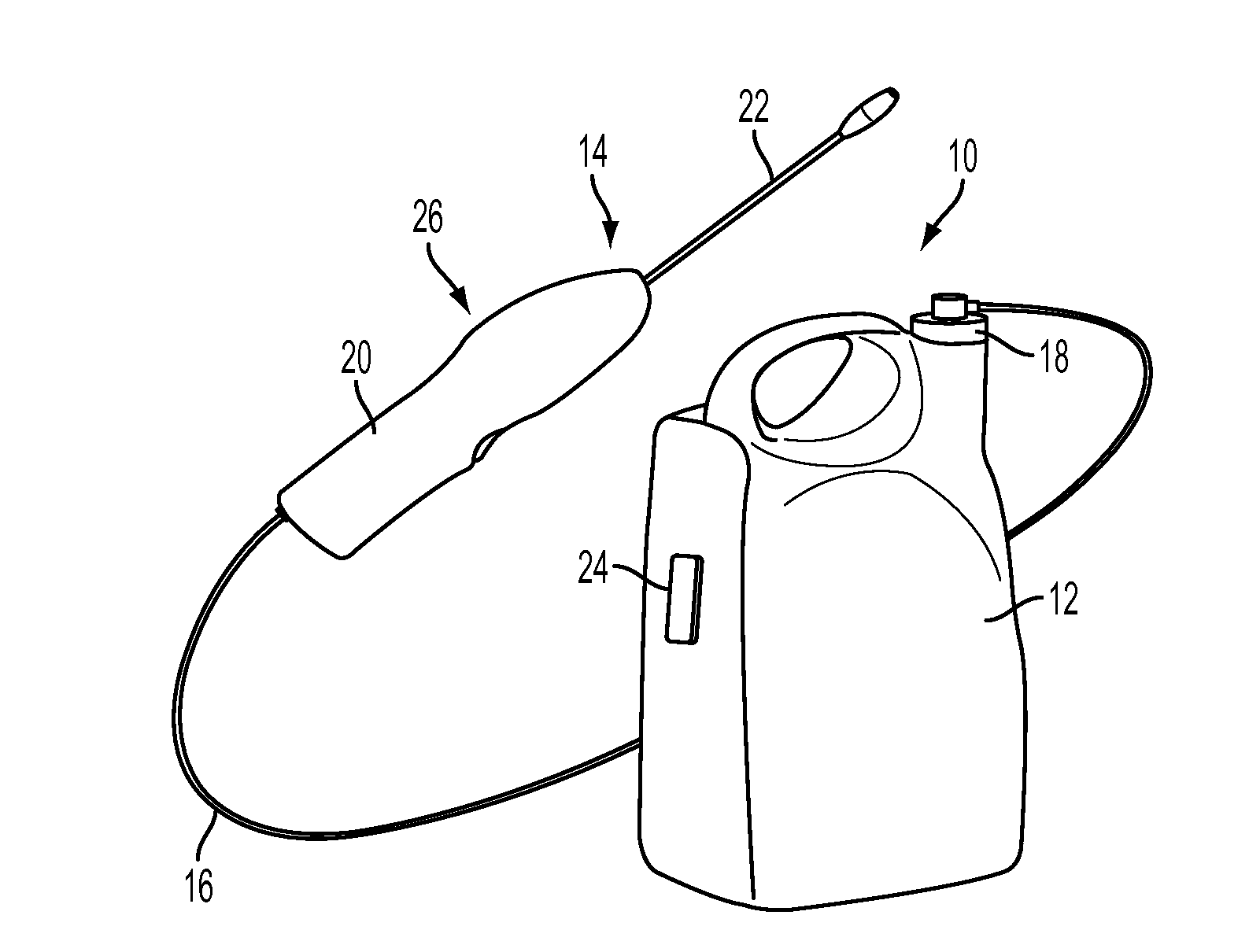
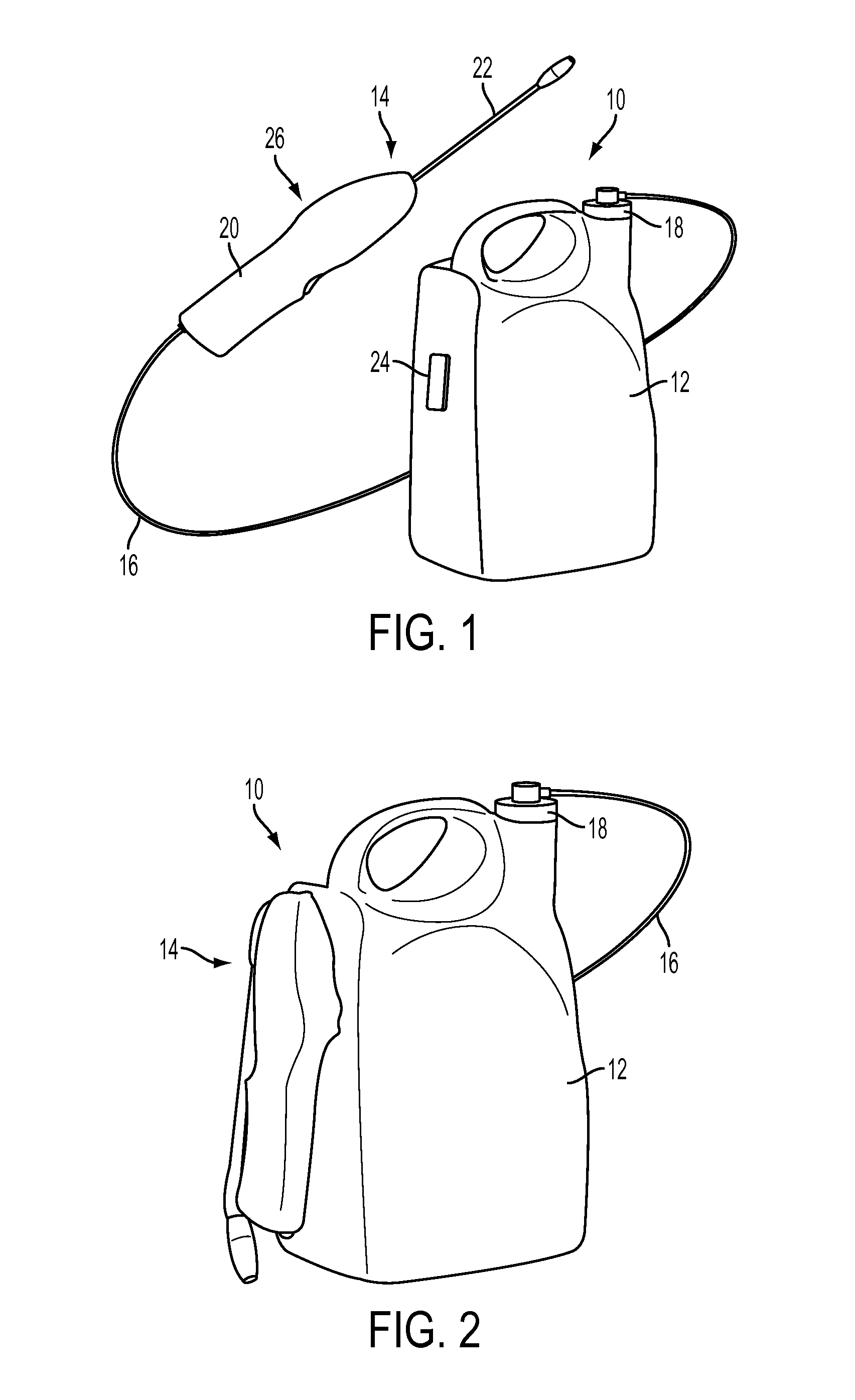
[0030]Referring now to the drawings wherein like reference numerals refer to like parts throughout, there is seen in FIGS. 1 and 2 a sprayer system designated generally by reference numeral 10 essentially comprising container 12 and spray wand 14 fluidly connected to container 12 by flexible hose 16. More specifically, flexible hose 16 extends between wand 14 and a cap 18 positioned on top of container 12.

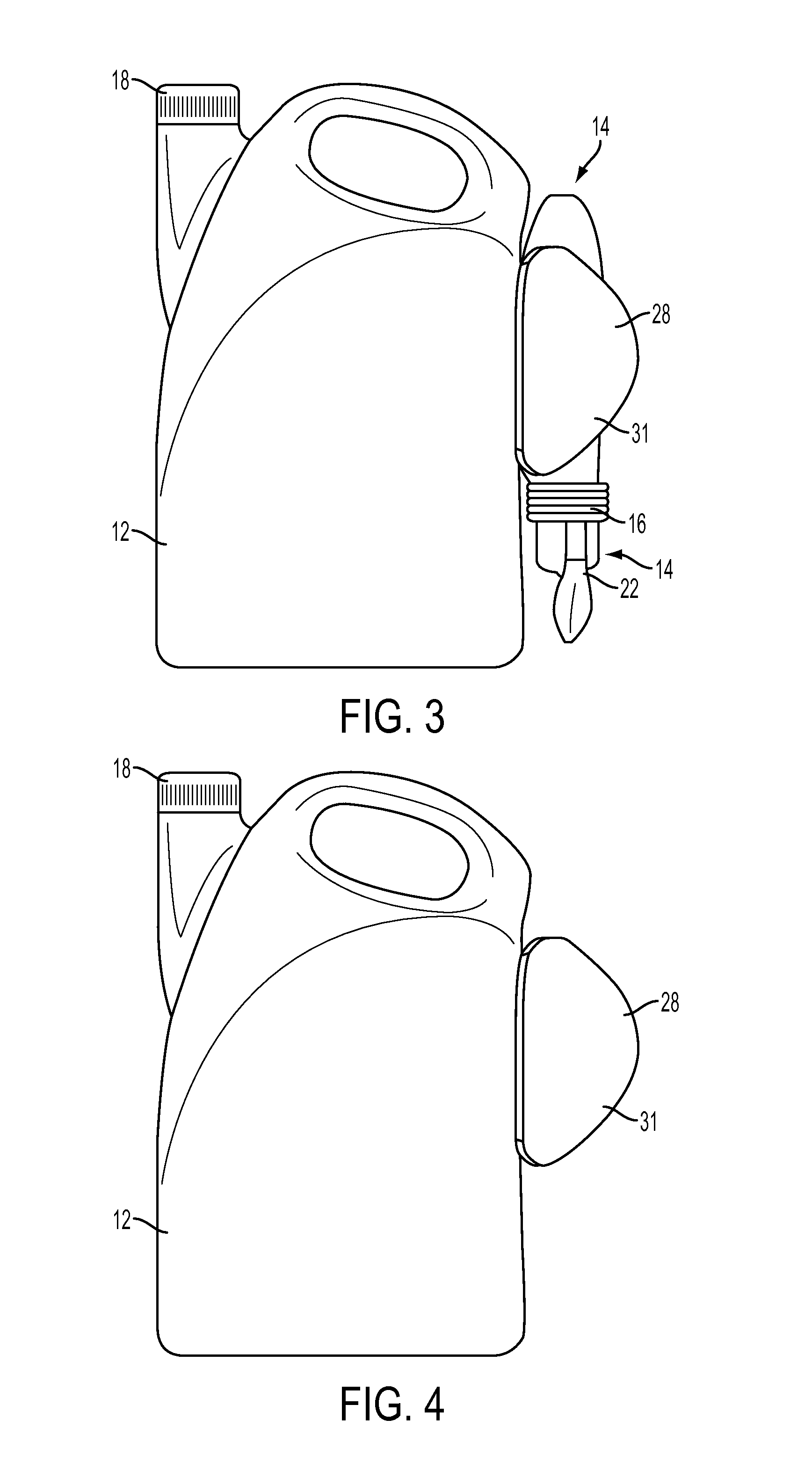
[0031]Spray wand 14 comprises a handle / wand housing 20 and wand portion 22 that is telescopically attached to handle 20 for sliding movement between stored (non-operational) and extended (operational) positions. A lug 24 is formed on the rear wall of container 12 and provides a mounting point for spray wand 20. Handle 20 includes a slot 26 formed therein that is sized and shaped to securely slidingly engage lug 24 from the top, thereby permitting spray wand 14 to be stored on container 12 with wand portion 22 facing downward during shipment / display and when not in use and stored aw...


PUM


Abstract

A lawn and garden sprayer system having a container and a spray wand fluidly connected to the container is provided. The spray wand includes a wand housing that has a slot formed in one side thereof that is configured to engage a lug formed on one side of the container for purposes of stowing the wand during shipping and when not in use. A communications card assembly is detachably connected between the container and spray wand during shipment and prior to its first use. The hose includes a coupler end that engaged a cap on the container and facilitates creation of a fluid circuit between the fluid contents in the container and the wand.

Description

REFERENCE TO RELATED APPLICATION[0001]The present application relates and claims priority to Applicant's U.S. Provisional Patent Application Ser. No. 61 / 876,379, filed Sep. 11, 2013, the entirety of which is hereby incorporated by reference.BACKGROUND[0002]1. Field of Invention[0003]The present invention relates generally to lawn and garden sprayers.[0004]2. Background of Art[0005]Lawn or garden sprayers use pressure to apply liquid fertilizers, pesticides, or other chemicals. A recent development is to utilize a battery-powered electric motor in the sprayer wand to provide the spraying pressure, rather than hand pumping.[0006]For present-day sprayers packaged at point of sale, the wand and its hose are stored separately from the sealed container and held in a separate “holster” carry device that is attached to the container, with the wand pointing up. Once the wand and hose are unpackaged and assembled for use, the holster may then be used for continued carry and storage of the wan...

Claims


Application Information

Patent Timeline
Patent Type & Authority Applications(United States)
IPC IPC(8): A01M7/00B05B11/00F16L37/40
CPCA01M7/0046F16L37/40B05B11/0008B05B11/3042B05B11/0005B05B9/0426B05B9/0861B05B15/63A01C15/02A01C23/047B05B12/002
Inventor MITCHELL, GEORGE A.RESTIVE, MARIO J.
Owner THE FOUNTAIN HEAD GROUP INC
Learn More