
Noise compensated fiber optic sensing systems and methods of operating the same

a fiber optic sensing and noise compensation technology, applied in the direction of optically converting sensor output, converting sensor output, instruments, etc., can solve the problems of introducing complexities in analysis, fiber optic sensing systems are subject to various sources of nois

Inactive Publication Date: 2015-05-14
SQUARE 1 BANK
View PDF0 Cites 8 Cited by
  • Summary
  • Abstract
  • Description
  • Claims
  • Application Information

AI Technical Summary

Benefits of technology

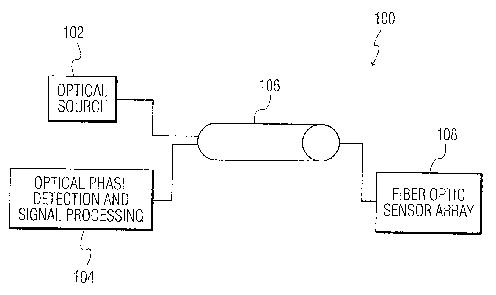
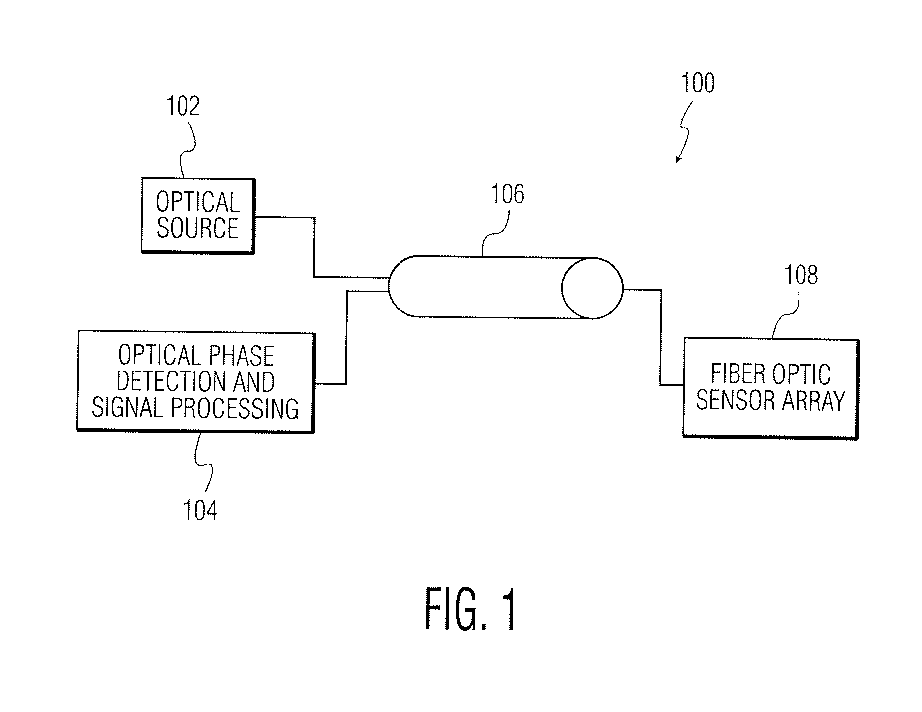
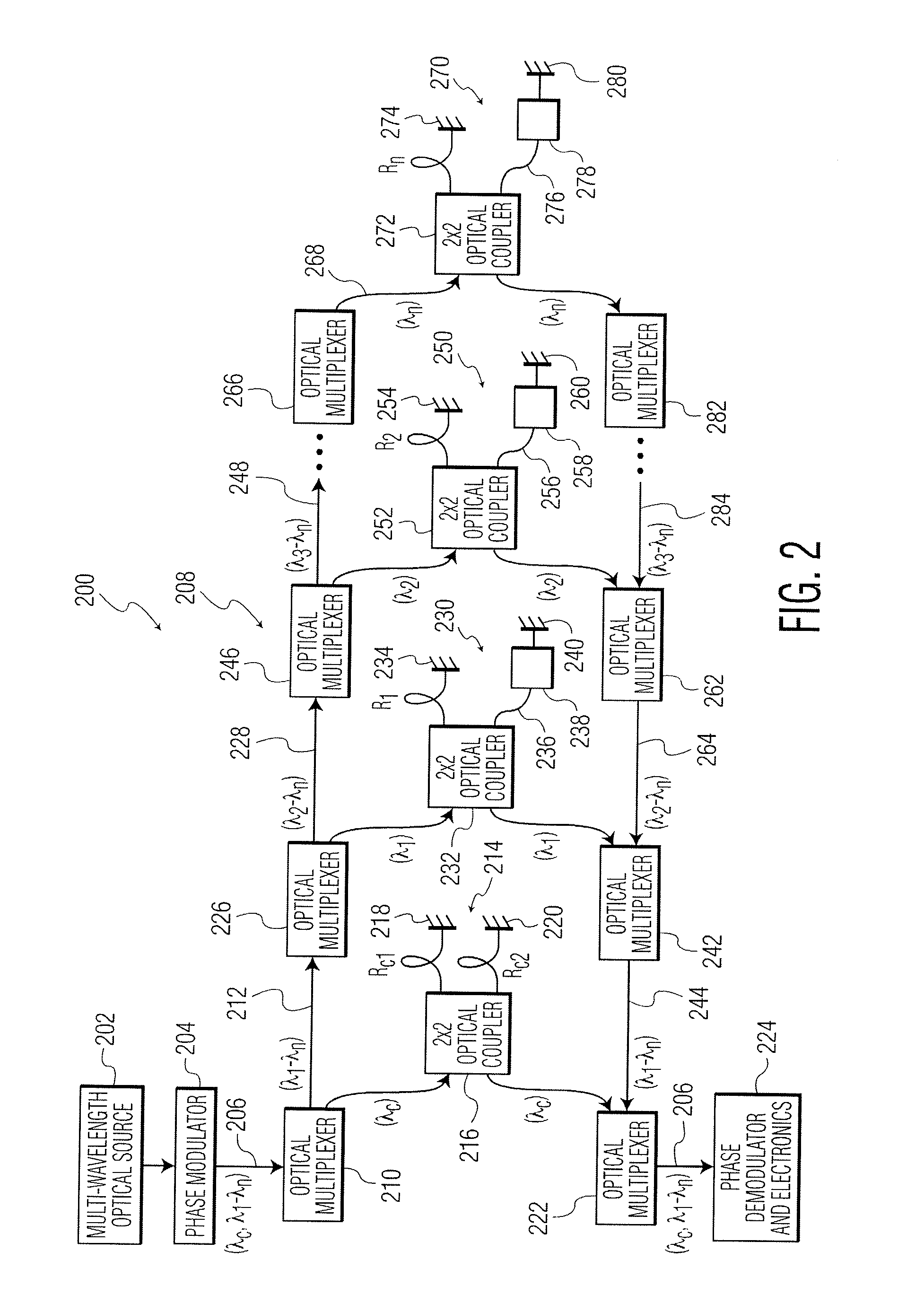
The present invention provides fiber optic sensing systems that include a sensor array and an optical source for transmitting optical signals. The sensor array includes multiple fiber optic sensors, each containing an interferometer with two legs. One of the legs of the interferometer is designed to sense vibration and is used as a noise compensation sensor. The other interferometer leg is insensitive to physical perturbations and serves as a reference for removing information unrelated to the physical quantity being measured. The invention also includes methods of operating and compensating for noise in the fiber optic sensing system. The technical effects of this invention are improved accuracy and reliability of fiber optic sensing systems that can measure physical quantities with high precision.

Problems solved by technology

Such fiber optic sensing systems are subject to various sources of noise that are indistinguishable from the primary measurable quantity of interest.
Such noises introduce complexities in the analysis of signals returned from the sensing portion of fiber optic sensing systems.

Method used


Image

  • Noise compensated fiber optic sensing systems and methods of operating the same
  • Noise compensated fiber optic sensing systems and methods of operating the same
  • Noise compensated fiber optic sensing systems and methods of operating the same

Examples


Embodiment Construction

[0015]As will be explained in greater detail below, according to certain exemplary embodiments of the present invention, improved systems and methods for compensating for noise (e.g., lead cable noise, optical source noise, etc.) in fiber optic sensing systems are provided. In certain exemplary fiber optic sensing systems (including interferometer-based sensing systems), an additional “dead” fiber optic sensor (e.g., an interferometer-based sensor where the additional sensor / interferometer is only sensitive to noise, and not to the primary measurable quantity of interest) is included in the fiber optic sensor system. The purpose of this dead sensor is to detect only noise common to the other “active” sensors. In one exemplary embodiment of the present invention, hardware or software compensation of the output data from the active sensors is accomplished by use of the demodulated output from the dead sensor (e.g., see FIG. 2). In another exemplary embodiment of the present invention,...


PUM


Abstract

A fiber optic sensing system. The fiber optic sensing includes an optical source and a lead cable for receiving an optical signal from the optical source. The fiber optic sensing system also includes a sensor array for receiving the optical signal from the lead cable. The sensor array includes a plurality of fiber optic sensors, each of the plurality of fiber optic sensors including an interferometer having two legs. The plurality of fiber optic sensors includes a noise compensation sensor. Each of the legs of the interferometer of the noise compensation sensor is configured to sense vibration in substantially the same manner.

Description

RELATED APPLICATION[0001]This application claims the benefit of priority to U.S. Provisional Patent Application Ser. No. 61 / 682,795, filed on Aug. 14, 2012, the contents of which are incorporated in this application by reference.TECHNICAL FIELD[0002]The field of the invention relates to apparatuses and methods that compensate for noise within a fiber optic sensing system and, more particularly, to using a noise compensation sensor in connection with such apparatuses and methods.BACKGROUND OF THE INVENTION[0003]Fiber optic sensing systems are utilized in various applications such as, for example, seismic sensing. Interferometer-based sensors are often used in such fiber optic sensing systems to sense information about a physical quantity being measured (e.g., temperature, pressure, etc.). Such fiber optic sensing systems are subject to various sources of noise that are indistinguishable from the primary measurable quantity of interest. As used in this document, the term “noise” may r...

Claims


Application Information

Patent Timeline
IPC IPC(8): G01D5/353G01D18/00
CPCG01D18/00G01D5/35303G01P15/093G01D5/35325
Inventor GOLDNER, ERIC L.BAKER, GERALD ROBERT
Owner SQUARE 1 BANK
Learn More