Flexible cable assembly for high-power switch gear

a high-power switch and flexible technology, applied in the direction of electrical equipment, contact mechanisms, substation/switching arrangement details, etc., can solve the problems of difficult to determine whether the adjustment is correct, and the adjustment of the jam nuts can be relatively difficult, so as to achieve precise torque

Active Publication Date: 2015-05-14
ROCKWELL AUTOMATION TECH
View PDF9 Cites 8 Cited by
  • Summary
  • Abstract
  • Description
  • Claims
  • Application Information

AI Technical Summary

Benefits of technology

[0008]The invention provides an improved actuator allowing single point adjustment of the attachment of the flexible cable sheath to the actuator housing, e

Problems solved by technology

Adjusting these jam nuts can be relatively difficult requiring partial disassembly of the actuator framework and working within the close confines of that framework to loosen and tighten these two nuts.
After moving

Method used


Image

  • Flexible cable assembly for high-power switch gear
  • Flexible cable assembly for high-power switch gear
  • Flexible cable assembly for high-power switch gear

Examples


Embodiment Construction

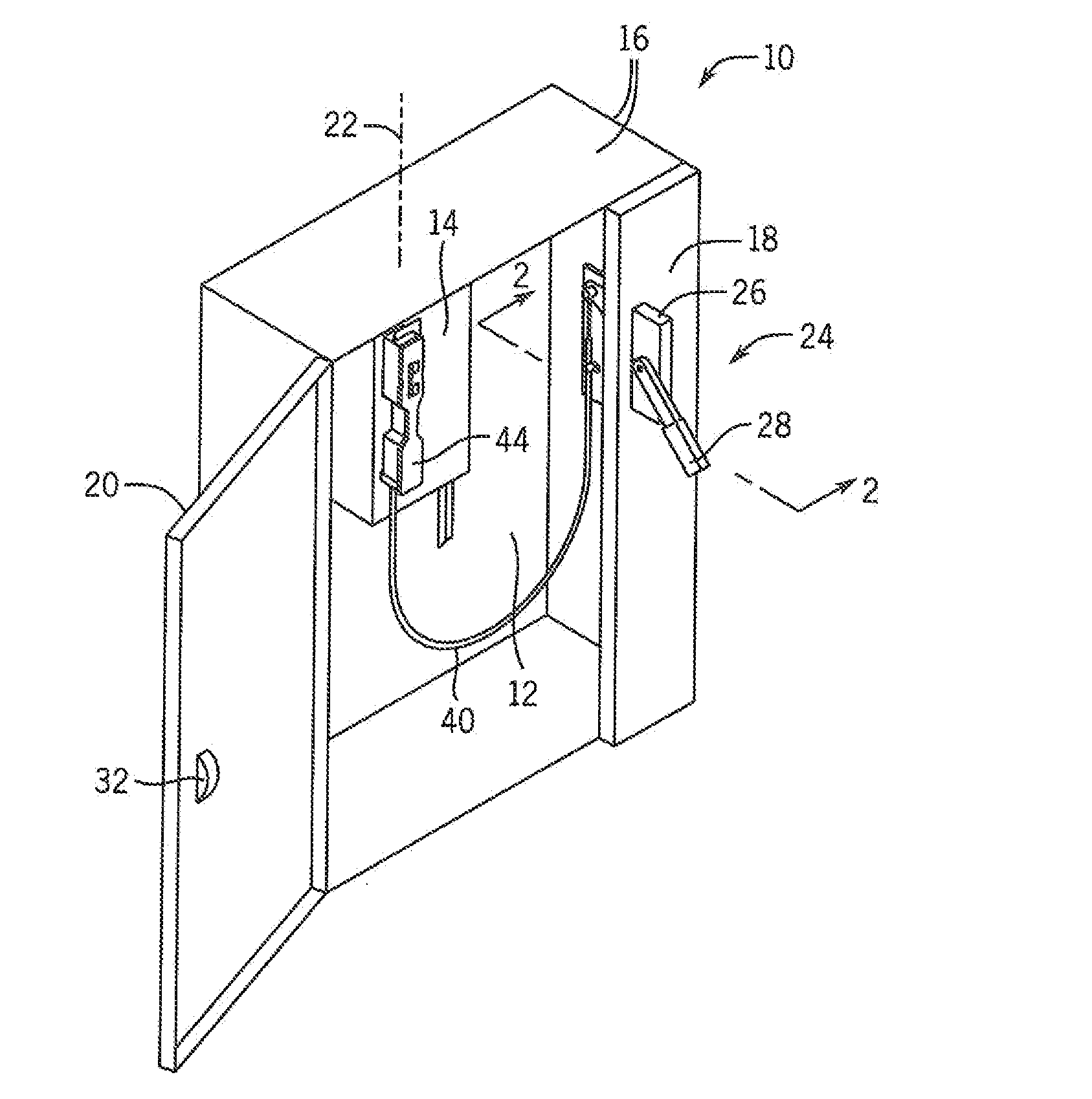
[0053]Referring now to FIG. 1, an electronics cabinet 10, for example, constructed of sheet steel, may provide a generally rectangular rear wall 12 to which electrical equipment may be attached including an electrical switch 14 such as a circuit breaker, disconnect switch, or the like. Top and side walls 16 of the electronic cabinet 10 extend forward from the periphery of the rear wall 12 and may be covered by a combination of the front panel 18 and door 20 to define a cabinet interior. The door 20 may hinge between open and closed position, for example, alone, a hinge axis 22 at a front vertical edge of left side wall 16.

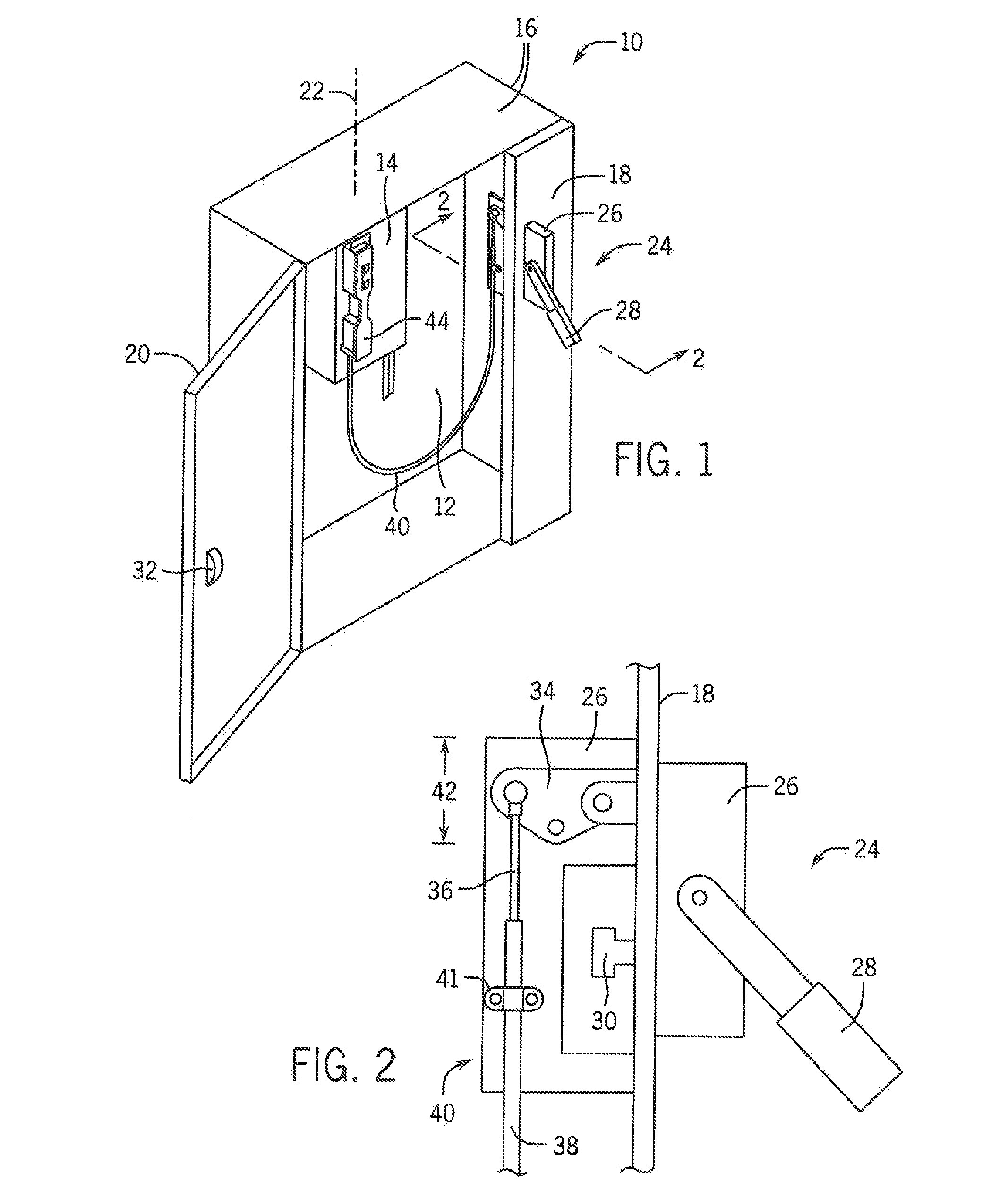
[0054]The front panel 18 may be fixed to one edge of the cabinet 10 against a left side wall 16 and spanning an upper and lower side wall 16 and may support a handle assembly 24. The handle assembly 24 may include a frame 26 supporting a pivoting handle 28 which may swing between an upper “on” position and a lower “off” position (the latter shown in FIG. 1) as mani...


PUM


Abstract

A remote switching system for electronic switches in a cabinet provides an actuator assembly communicating through a flexible cable with a door handle. The actuator assembly on the electronic switch provides a rotatably captive threaded fastener holding the sheath of the flexible cable to the actuator assembly allow ring a simple single-point tuning of the actuator operation. This tuning may be facilitated by a visual scale showing relative positions between the actuator assembly and an internal slider communicating with the operator of the electronic switch.

Description

BACKGROUND OF THE INVENTION[0001]The present invention relates to high-power electrical switches, and in particular to a flexible cable operator for remotely actuating electrical switches such as circuit breakers.[0002]High-power electrical circuitry is normally placed inside a metal cabinet to protect the electrical circuitry from the external environment and to shield users from potential hazards associated with the operation of the circuitry.[0003]Often the cabinet provides a handle that serves both to lock a cabinet door and to disconnect electrical power from the interior circuitry before the door is opened. The handle may communicate through a flexible cable operator with a switch inside the cabinet, for example, a circuit breaker, so that when the handle is moved to allow opening of the cabinet door, the circuit breaker is also opened, removing electrical power from the interior circuitry. This feature is normally subject to the mechanical override in the event that the cabin...

Claims


Application Information

Patent Timeline
IPC IPC(8): H01H3/02
CPCH01H3/02H01H9/22H01H3/20H01H3/38
Inventor CLORAN, SHAWN D.BYALIY, EDWARDWATKINS, JERRY M.LASKO, SCOTT B.MILLER, JAMES P.WIELOCH, CHRISTOPHER J.
Owner ROCKWELL AUTOMATION TECH
Why Eureka
Try Eureka