Method and apparatus for monitoring mechanical fiber stress of optical fiber spans

a technology of mechanical fiber and optical fiber, which is applied in the direction of fault measurement system, transmission monitoring/testing/measurement system, transmission, etc., can solve the problems of reducing the signal power

Active Publication Date: 2015-05-14
ADVA OPTICAL NETWORKING SE
View PDF7 Cites 9 Cited by
  • Summary
  • Abstract
  • Description
  • Claims
  • Application Information

AI Technical Summary

Benefits of technology

[0007]In a further possible embodiment of the method according to the first aspect of the present invention, if an observed phase shift of said timing phase within the...

Problems solved by technology

For instance, due to excavation activities, fibers of one or several fiber spans within a fiber link connecting two network elements of the network can be stretched and are at a risk of being cut by mechanical effects.
However, these conventional techniques are unreliable in pre...

Method used


Image

  • Method and apparatus for monitoring mechanical fiber stress of optical fiber spans
  • Method and apparatus for monitoring mechanical fiber stress of optical fiber spans
  • Method and apparatus for monitoring mechanical fiber stress of optical fiber spans

Examples


Embodiment Construction

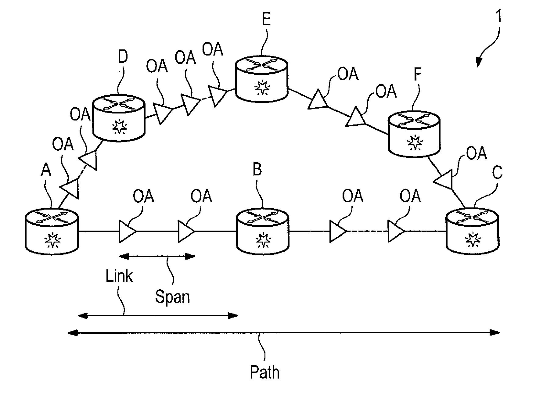
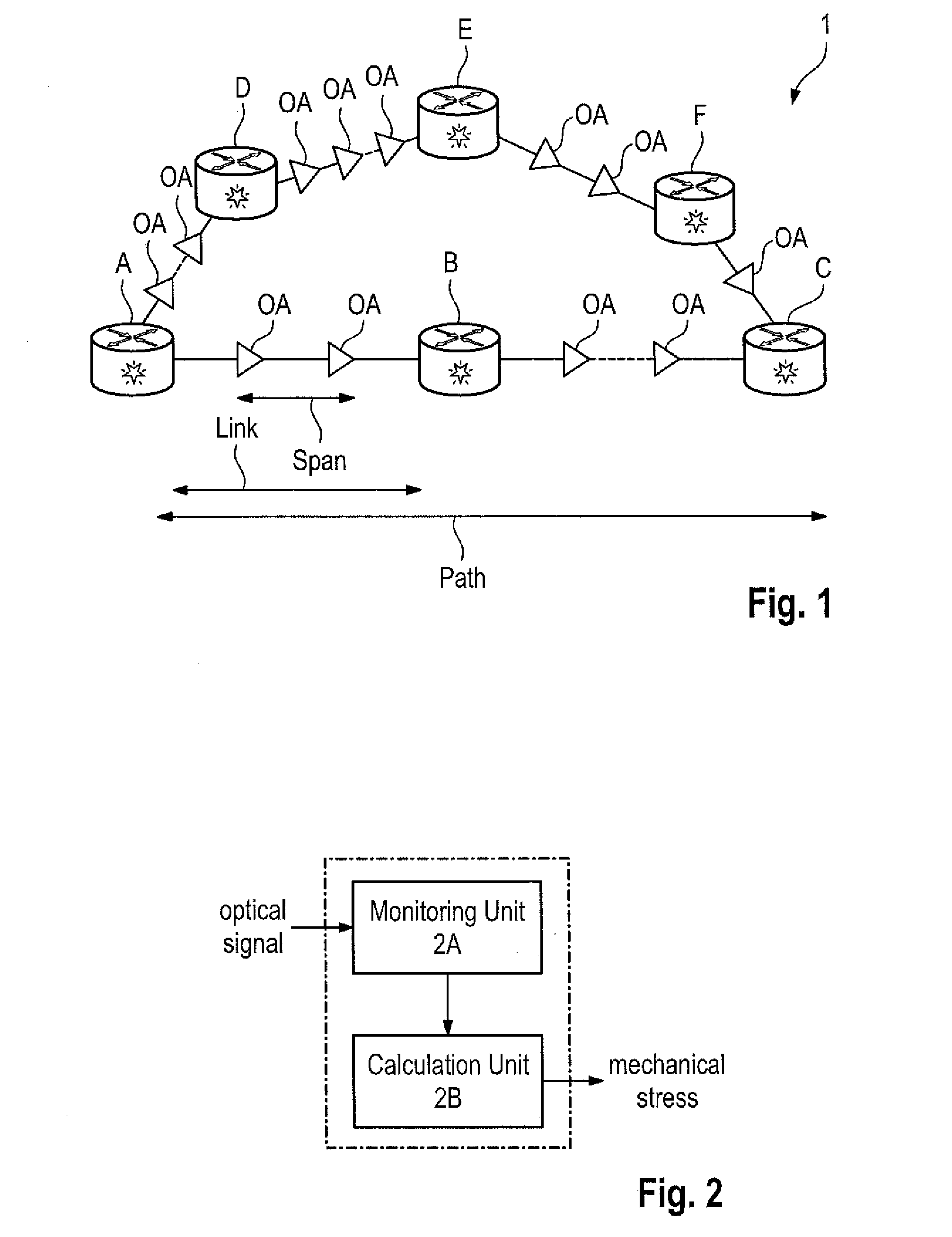
[0034]FIG. 1 shows an exemplary embodiment of an optical network 1 according to the present invention. The optical network 1 comprises a plurality of network elements connected to each other via optical links each being composed of one or more optical fiber spans. In the shown simple exemplary embodiment of the optical network 1, the network comprises network elements A, B, C, D, E, F. The optical network elements A to F can be formed by interfaces to routers, and are therefore the only locations in the optical network 1 where an optical signal can be either generated or terminated. The network elements A to F are connected together through optical fiber links which are composed of one or more optical fiber spans with or without amplification. For instance, network element A is connected to the network element B via an optical fiber link AB. The link is composed of one or several optical fiber spans, wherein after each of the spans the optical signal is regenerated either optically ...


PUM


Abstract

The length of the optical fiber section under tension expands by a certain amount that is proportional to the level of tension applied to it. Monitoring the variations in the phase of the arriving signal allows to discover a fiber that is subject to a certain level of mechanical tension. With the method and apparatus according to the present invention it is possible to protect optical communication channels against failures in an optical transmission fiber that are caused by any kind of mechanical disturbances.

Description

TECHNICAL BACKGROUND[0001]The invention relates to a method and apparatus for monitoring mechanical fiber stress of optical fiber spans within an optical network, and in particular to a method and apparatus for predicting an optical fiber cut event.[0002]An optical network comprises a plurality of network elements connected to each other via optical links. Each optical link can be composed of one or several optical fiber spans comprising optical fibers. Optical fiber spans can be subject to mechanical stress. For instance, due to excavation activities, fibers of one or several fiber spans within a fiber link connecting two network elements of the network can be stretched and are at a risk of being cut by mechanical effects. Conventional techniques used nowadays for predicting fiber cuts are based on monitoring for any degradation in the bit error rate of a signal received by a receiver and / or a drop in the optical power of the received signal. However, these conventional techniques ...

Claims


Application Information

Patent Timeline
IPC IPC(8): H04B10/077H04B10/25H04J14/02H04B10/27
CPCH04B10/0775H04B10/0771H04J14/02H04B10/25H04B10/27G01M11/088H04B10/073H04B10/077
Inventor ALFIAD, MOHAMMADFILER, MARKRABENKO, TEDTIBULEAC, SORIN
Owner ADVA OPTICAL NETWORKING SE
Why Eureka
Try Eureka