
Shield and locking type board to board connector

a shielding type, locking type technology, applied in the direction of coupling contact members, coupling device connections, electrical devices, etc., can solve the problems of easy to forget when the assembly of the connector unit is complete, and easy to assemble the connector unit. , to achieve the effect of improving the reworkability of the connector, facilitating easy size design, and improving the mechanical strength of the shell-shaped shield member

Active Publication Date: 2015-05-14
UJU ELECTRONICS
View PDF6 Cites 20 Cited by
  • Summary
  • Abstract
  • Description
  • Claims
  • Application Information

AI Technical Summary

Benefits of technology

The connector in this invention has the following advantages: it is stronger, easier to design, and can be easily locked. This makes it more durable and flexible in use.

Problems solved by technology

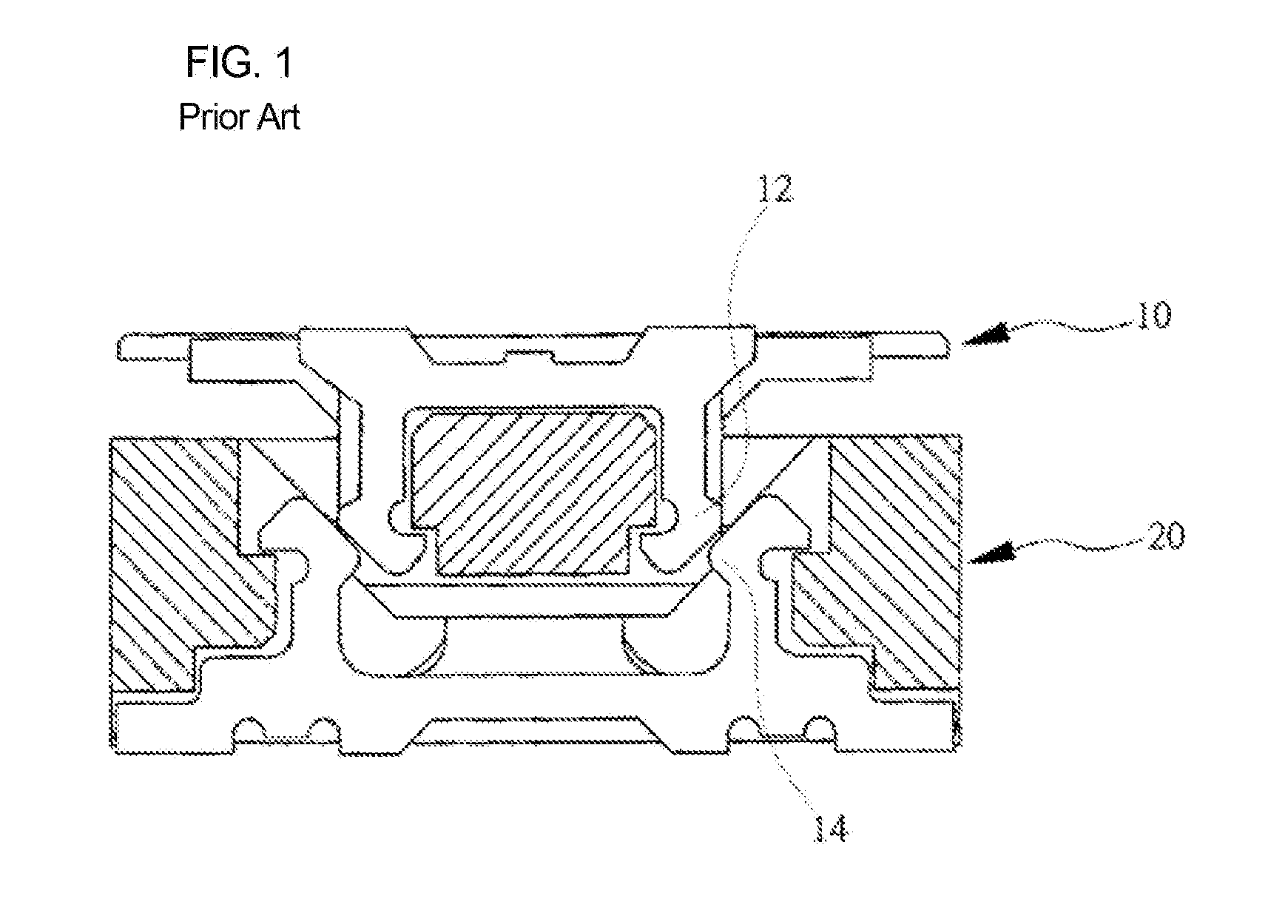
However, after being assembled, the two connector units 10 and 20 may be undesirably disassembled from each other by an external force.
Further, during a process of assembling the male and female connector units, it is not easy to know when assembly of the connector units is complete by vibrations, noise, or a so-called “click” when the units are “snapped” into place.
In an effort to solve the problems experienced in the conventional technology, the sizes and shapes of the snap protrusions may be somewhat exceedingly changed such that the change in the sizes and shapes of the protrusions can induce firm snapping of the protrusions and can generate a snap shock or snap noise.
However, the change in the sizes and shapes of the protrusions is problematic in that the protrusions may not easily snap to each other.
Further, when the connector units are assembled or disassembled, the snap protrusions having exceedingly changed sizes and shapes may be undesirably deformed or broken.
Accordingly, when disassembling the male and female connectors so as to repair a device mounted on a circuit board, the connector units may be broken or devices soldered to boards, such as PCBs, may be undesirably separated from the boards.

Method used


Image

  • Shield and locking type board to board connector
  • Shield and locking type board to board connector
  • Shield and locking type board to board connector

Examples


Embodiment Construction

[0047]Before the present invention is described in detail, it should be noted that the present invention may be embodied in many different forms without departing from the spirit and significant characteristics of the present invention. Therefore, the embodiments of the present invention are disclosed only for illustrative purposes and should not be construed as limiting the present invention.

[0048]It will be understood that, although the terms “first,”“second,” etc. may be used herein to describe various elements, these elements should not be limited by these terms.

[0049]These terms are only used to distinguish one element from another element. For instance, a first element discussed below could be termed a second element without departing from the teachings of the present invention. Similarly, the second element could also be termed the first element.

[0050]It will be understood that when an element is referred to as being “coupled” or “connected” to another element, it can be dire...


PUM


Abstract

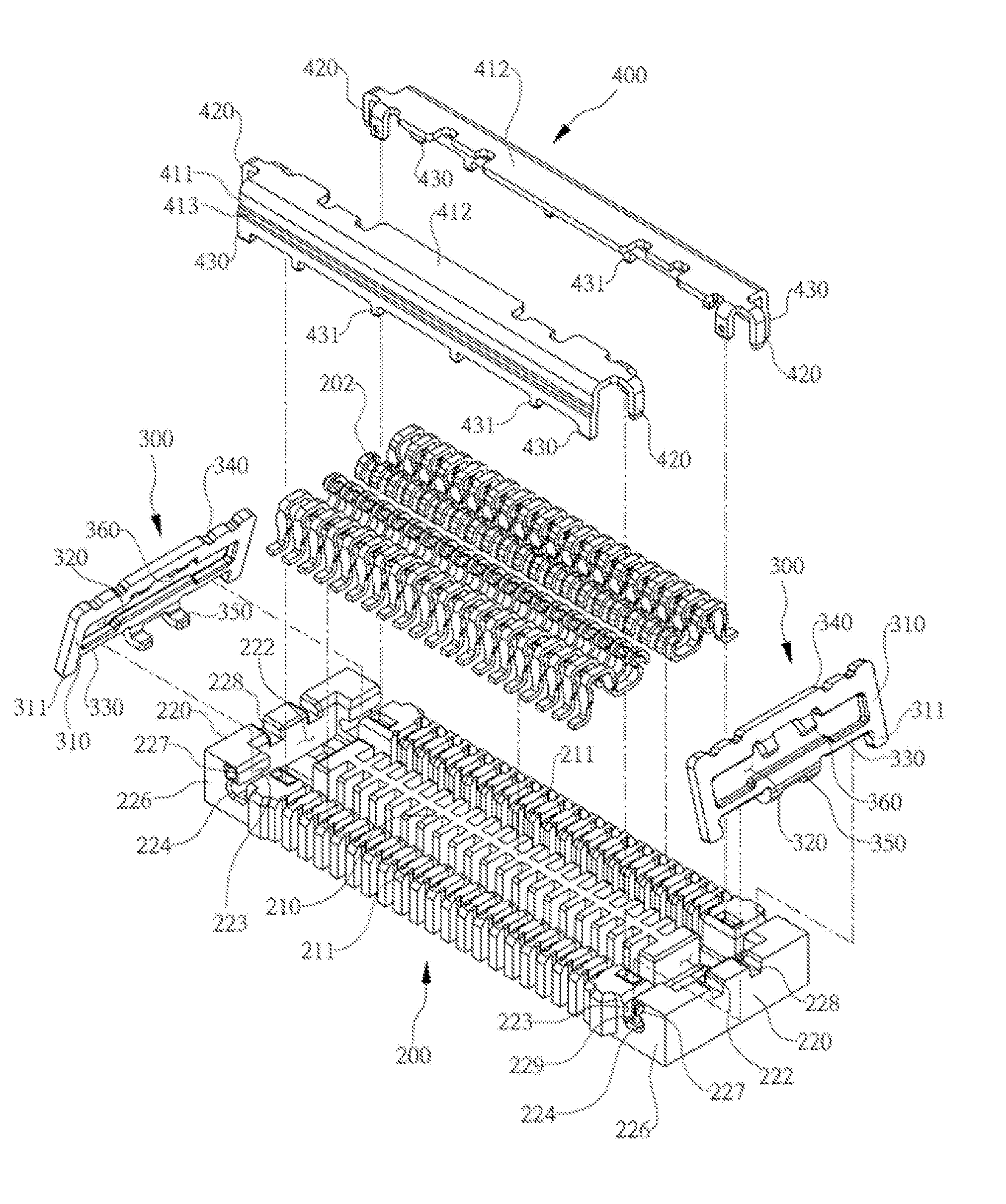
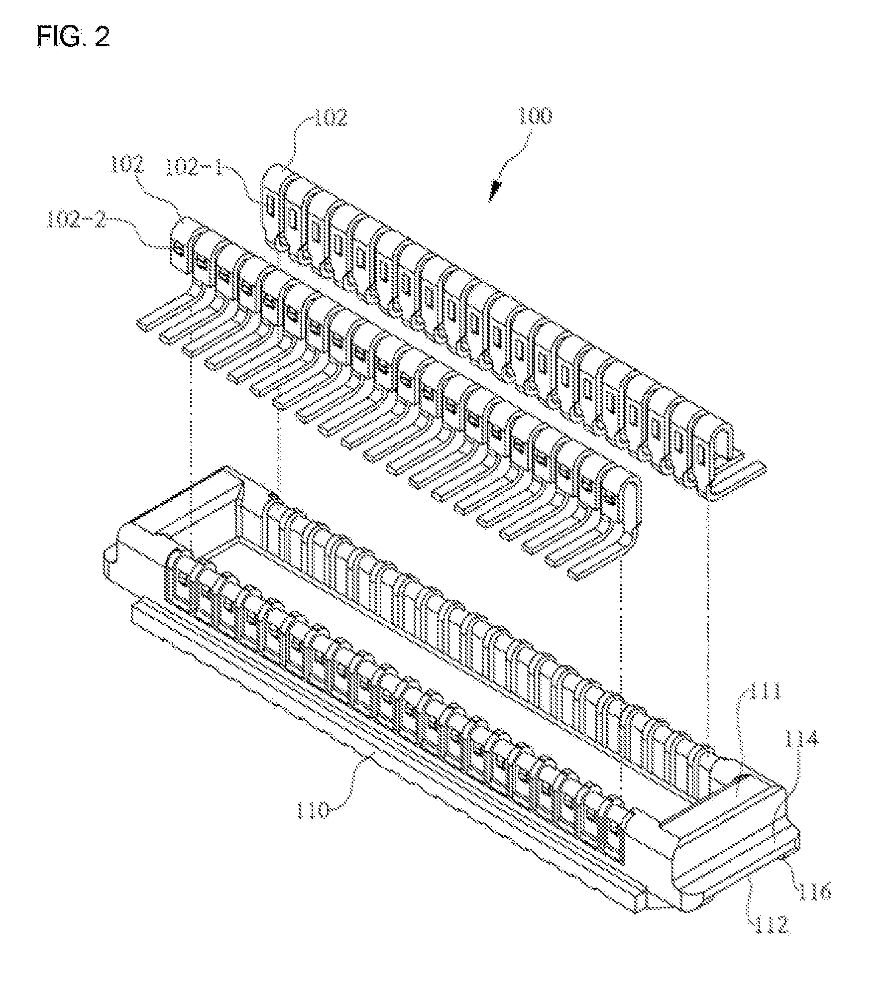
A shield and locking type board to board connector functioning to connect a first board and a second board to each other, the connector including: a first connector unit having both a first base and a first terminal; a second connector unit having a second base and a second terminal; two shield members each having a shell shape, the shield members respectively provided on front and rear bases facing the second base such that the shield members arrest EMI (electromagnetic interference) noise; and a locking member provided in the second connector unit so as to prevent the first connector unit from being removed outward by an outward movement thereof after the first connector unit is combined with the second connector unit in a close contact state.

Description

CROSS REFERENCE[0001]This application claims foreign priority under Paris Convention to Korean Patent Application No. 10-2013-0135294, filed 8 Nov., 2013, with the Korean Intellectual Property Office.BACKGROUND OF THE INVENTION[0002]1. Field of the Invention[0003]The present invention relates, in general, to the construction of a board to board connector and, more particularly, to a shield and locking type board to board connector, which includes a shield member having a locking member stop part, and can avoid a generation of EMI (electromagnetic interference) that may be caused during an operation of the boards and can prevent undesired disassembly of a female connector unit and a male connector unit of the board to board connector after assembling the connector units.[0004]2. Description of the Related Art[0005]Generally, a board to board (BtoB) connector is used to connect circuit boards that are printed with a variety of circuits to each other. As shown in FIG. 1, the board to b...

Claims


Application Information

Patent Timeline
Patent Type & Authority Applications(United States)
IPC IPC(8): H01R13/627H01R13/6581
CPCH01R13/6581H01R13/627H01R12/73H01R13/6275H01R13/6335H01R13/20H01R13/631H01R12/71
Inventor CHOI, SUK-JINLEE, GUEN-O
Owner UJU ELECTRONICS
Learn More