
Ipg configured to deliver different pulse regimes to different leads for pudendal nerve stimulation

a pudendal nerve and pulse regime technology, applied in the field of stimulation systems, can solve the problems of inability to know how well a stimulation lead is implanted, requiring too much clinician involvement, and high cost, so as to improve the efficacy of sacral nerve stimulation therapy, and reduce the cost of implanting

Active Publication Date: 2015-05-14
CIRTEC MEDICAL CORP
View PDF8 Cites 29 Cited by
  • Summary
  • Abstract
  • Description
  • Claims
  • Application Information

AI Technical Summary

Benefits of technology

The present patent relates to a medical system for treating a patient using sacral nerve stimulation therapy. The system includes an implantable lead with electrode contacts, a pulse generator, and a portable electronic programmer. The electronic programmer generates an electronic diary based on input from the patient and detects a loss of efficacy of the therapy based on voiding responses in the diary. The system automatically adjusts the therapy by identifying predefined stimulation programs or a second subset of electrode contacts that improve the efficacy of the therapy. The technical effect of this patent is to improve the efficacy of sacral nerve stimulation therapy by automatically adjusting the therapy based on the patient's response to the therapy.

Problems solved by technology

For example, they may be expensive to carry out and may require too much clinician involvement.
As another example, it may be difficult to know how well a stimulation lead is implanted.
As another example, conventional sacral nerve stimulation systems typically require a one-to-one correspondence between stimulation channels and electrode contacts, which may be expensive and cumbersome to handle.
Therefore, although existing sacral nerve stimulators are generally adequate for their intended purposes, they have not been satisfactory in all respects.

Method used


Image

  • Ipg configured to deliver different pulse regimes to different leads for pudendal nerve stimulation
  • Ipg configured to deliver different pulse regimes to different leads for pudendal nerve stimulation
  • Ipg configured to deliver different pulse regimes to different leads for pudendal nerve stimulation

Examples


Embodiment Construction

[0038]It is to be understood that the following disclosure provides many different embodiments, or examples, for implementing different features of the invention. Specific examples of components and arrangements are described below to simplify the present disclosure. These are, of course, merely examples and are not intended to be limiting. Various features may be arbitrarily drawn in different scales for simplicity and clarity.

[0039]Before any embodiments of the invention are explained in detail, it is to be understood that the invention is not limited in its application to the details of construction and the arrangement of components set forth in the following description or illustrated in the following drawings. The invention is capable of other embodiments and of being practiced or of being carried out in various ways.

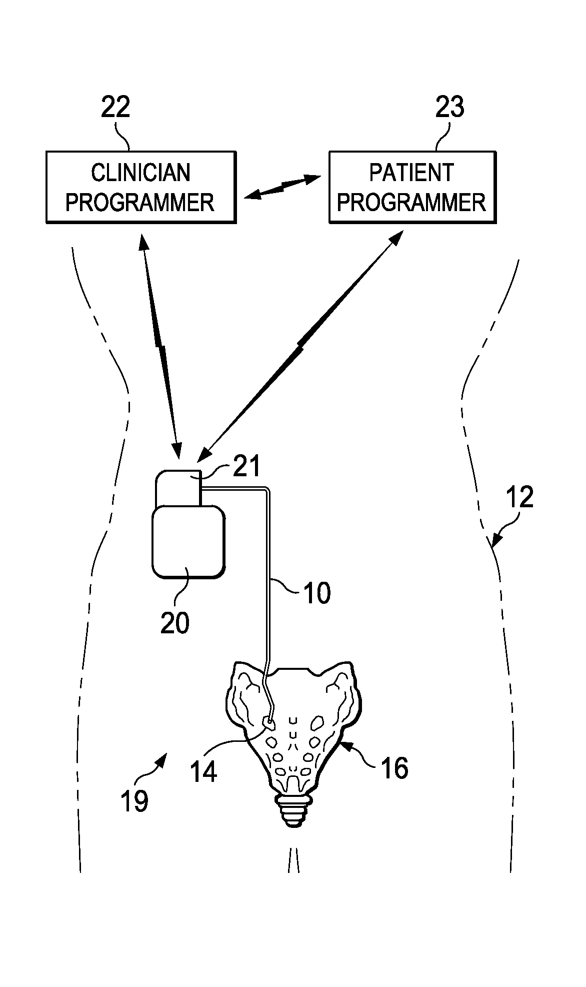
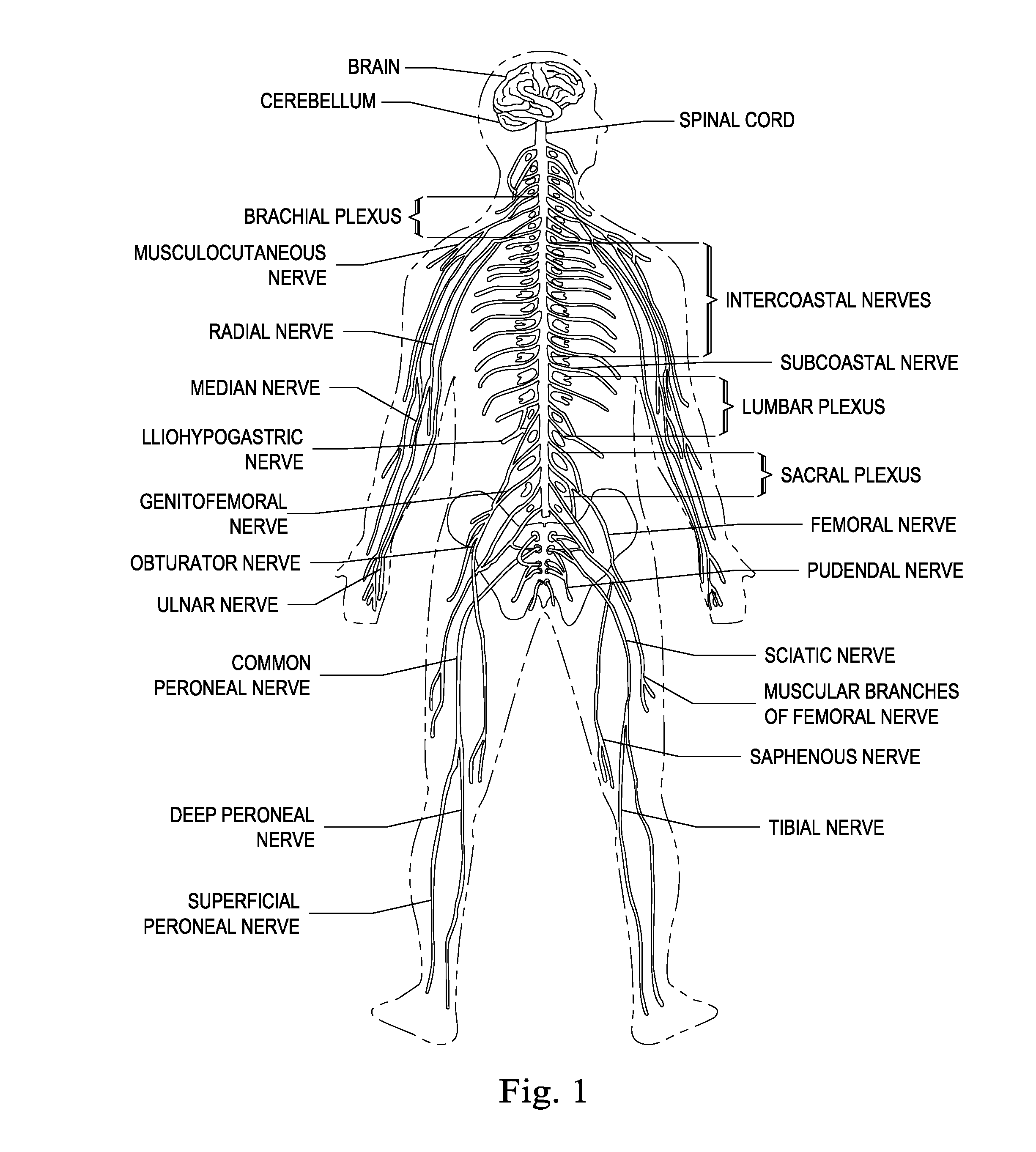
[0040]The human nervous system includes a complex network of neurological structures that extend throughout the body. As shown in FIG. 1, the brain interconnects w...


PUM


Abstract

The present disclosure involves a method of generating different stimulation waveforms as a part of sacral nerve stimulation therapy. A first stimulation waveform having a first stimulation waveform characteristic is generated. The first stimulation waveform is delivered to a first body part of a patient at least in part via a first channel. A second stimulation waveform having a second stimulation waveform characteristic is generated. The second stimulation waveform characteristic is different from the first stimulation waveform characteristic. The second stimulation waveform is delivered to a second body part of the patient at least in part via a second channel that is separate and independent from the first channel. The first body part and second body part correspond to different organs or different types of nerves.

Description

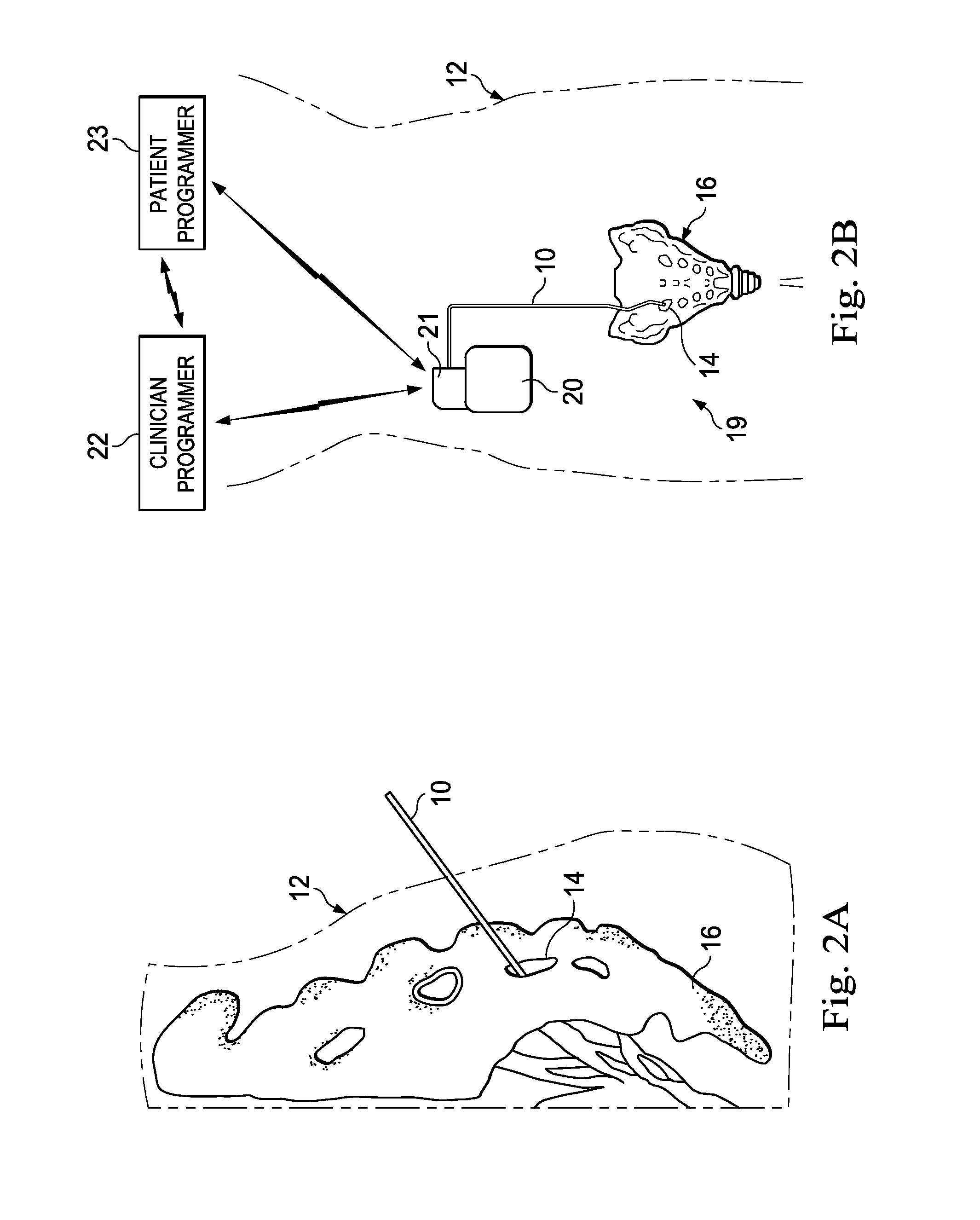
PRIORITY DATA[0001]The present application is a utility application of provisional U.S. Patent Application No. 61 / 901,499, filed on Nov. 8, 2013, entitled “Stimulation Apparatuses, Devices, Systems, and Methods,” and a utility application of provisional U.S. Patent Application No. 61 / 923,927, filed on Jan. 6, 2014, entitled “Stimulation Apparatuses, Devices, Systems, and Methods,” the disclosures of each of which are hereby incorporated by reference in their respective entireties.BACKGROUND[0002]The invention relates to a stimulation system, such as a sacral nerve stimulation system, having a tool for programming an electrical stimulation generator, such as an implantable pulse generator (IPG), of the system.[0003]A sacral nerve stimulator is a device used to provide electrical stimulation to the pelvic region of a patient, for example the sacral nerve or the pudendal nerve, in order to treat problems such as incontinence. The stimulator includes an implanted or external pulse gener...

Claims


Application Information

Patent Timeline
IPC IPC(8): A61N1/36A61N1/372
CPCA61N1/37235A61N1/36146A61N1/0551A61N1/0558A61N1/36007A61N1/36132A61N1/37247A61N1/0512A61N1/3606A61N1/05
Inventor KAULA, NORBERTIYASSU, YOHANNESLABBE, MICHAEL
Owner CIRTEC MEDICAL CORP
Learn More