
System for Production Boosting and Measuring Flow Rate in a Pipeline

a technology of pipeline flow rate and production boost, which is applied in the field of pipeline flow rate measurement system, can solve the problems of only testing wells, lack of measurement reliability, and discourage the use of multi-phase meters by many operators

Inactive Publication Date: 2015-05-21
CALTEC
View PDF11 Cites 8 Cited by
  • Summary
  • Abstract
  • Description
  • Claims
  • Application Information

AI Technical Summary

Benefits of technology

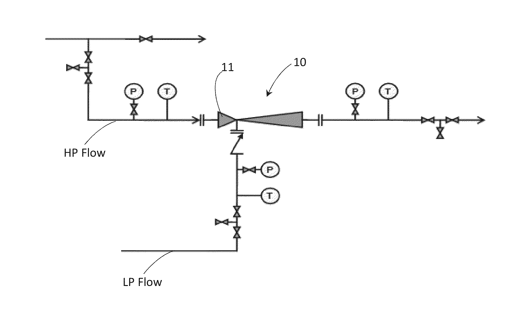
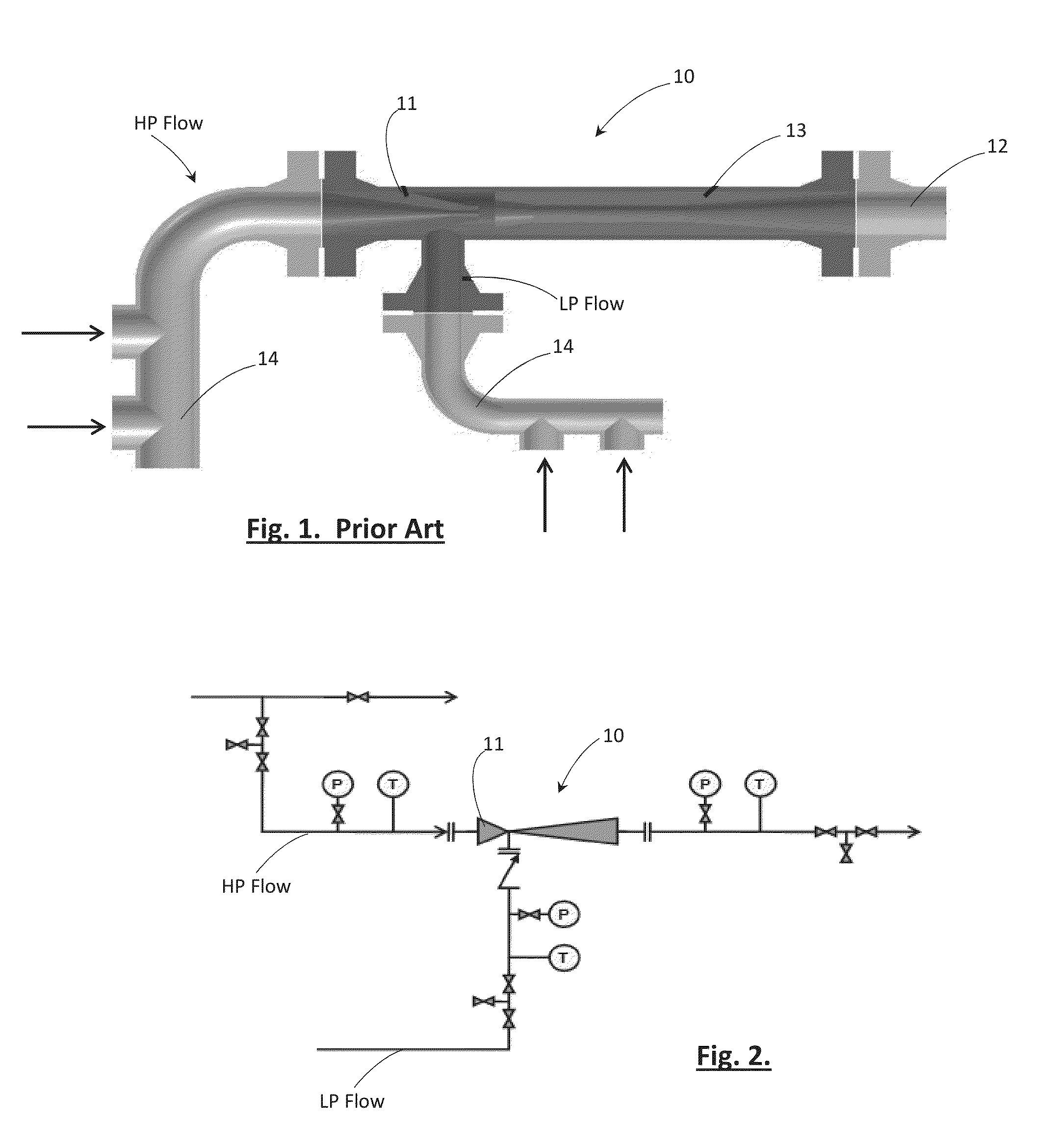
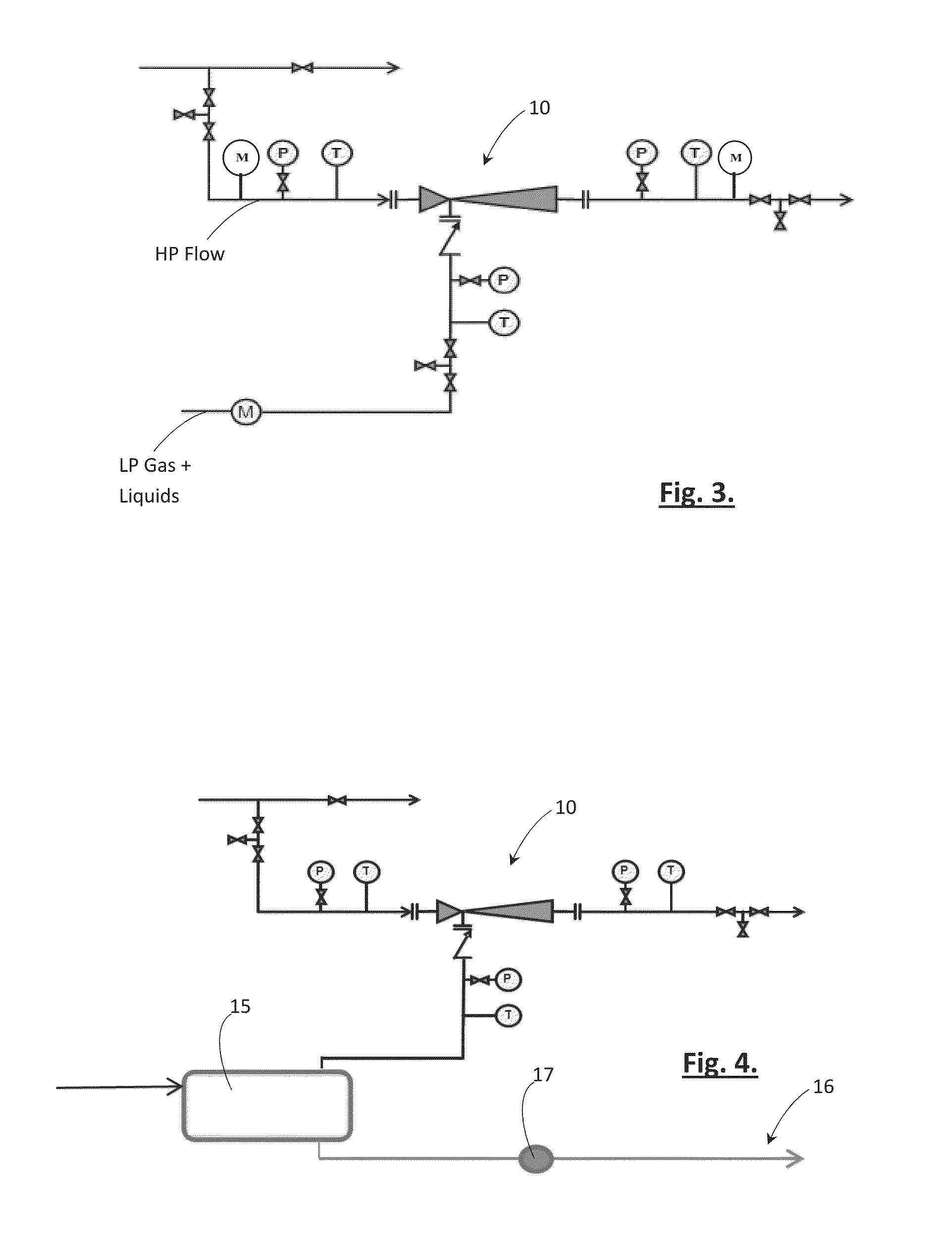
The present invention proposes a system for measuring flow rate in a pipeline using a surface jet pump (SJP) as a means of boosting production. The SJP is a passive device that does not require any active control or measurements, but there are often no flow meters available to estimate production rates. The invention proposes to use existing pressure sensors on the SJP to approximate flow rates based on correlations and cross-referencing the pressure values. The system can be verified and optimised by use of an actual flow meter but, in the field, the SJP monitored by existing sensors becomes a flow meter. The invention is applicable to gas wells which produce below 1% to 2% liquids by volume at conventional operating pressures and temperatures and use surface jet pumps to boost their production. The suggested limit for the liquid flow rate is due to the fact that within this range of liquids the performance of the SJP and values such as the pump's efficiency and the viscosity of the liquid are known. The invention provides a means of measuring fluid flow rates during production without the need for additional facilities or cost.

Problems solved by technology

It is known to install a multiphase meter instead of the test separator; however, there are a number of issues such as cost and lack of measurement reliability which discourage the use of multiphase meters by many operators.
In any event, in these cases the wells can only be tested at the pressures equal to or above the production pressure of the manifold.

Method used


Image

  • System for Production Boosting and Measuring Flow Rate in a Pipeline
  • System for Production Boosting and Measuring Flow Rate in a Pipeline
  • System for Production Boosting and Measuring Flow Rate in a Pipeline

Examples


case 1

[0036 shows the performance of the SJP with only LP gas passing through the SJP under a given motive (HP) pressure . The underlined values where calculated by the software. Case 2 shows the estimation of LP liquid flow rate when LP pressure and LP flowrates are entered along with other pressures. In these examples the software has predicted the LP liquid flow rate at the given LP gas flow rate and the measured LP pressure for each case with different LP flow rate.

[0037]FIGS. 5 and 6 provide example performance curves generated by software according to the invention (Table 1 was also generated by this software). In the example an SJP operates in the field with fairly clean fluids, for that particular geometry of the SJP, FIGS. 5 and 6 are the performance curves generated.

[0038]Referring to FIG. 5, a linear relationship is observed between pressure and flow rate for a given geometry, e.g. y=0.8643x+0.8252; R2=1. According to the graph, for the HP nozzle of the SJP, it is possible to r...


PUM


Abstract

A system for measuring flow rate in a pipeline by use of a surface jet pump that receives input from both a high pressure pipeline and a low pressure pipeline. Rather than installing flow meters at any or all of the inputs / output from the SJP which is an expensive undertaking, flow rate is predicted by utilising existing pressure sensors located on the high pressure pipeline, low pressure pipeline and discharge pipeline respectively. A control processor predicts flow rate based on correlations between flow rate and pressure for a given SJP geometry and, for example, utilises momentum, conservation of mass and continuity equations, balanced against the pressure forces and velocity in the SJP.

Description

CROSS-REFERENCE TO RELATED APPLICATIONS[0001]This application claims foreign priority benefits under 35 U.S.C. §119(a)-(d) to United Kingdom patent application number GB 1320202.3 filed Nov. 15, 2013, the disclosure of which is hereby incorporated in its entirety by reference in its entirety.TECHNICAL FIELD[0002]The present invention relates to a system for measuring flow rate in a pipeline and, specifically, configuring a surface jet pump (hereinafter “SJP”) as a means of measuring flow rate, in addition to its normal duty of pressure / production boosting.BACKGROUND TO THE INVENTION[0003]The measurement of fluid flow rates produced from a well is an important part of production management and assessment of reservoir behaviour. In many cases, such as offshore oil and gas production, a test separator is installed and production from each well can be diverted to the test separator for measurement of oil, water and gas. In most of such cases the wells can only be tested at the pressure ...

Claims


Application Information

Patent Timeline
Patent Type & Authority Applications(United States)
IPC IPC(8): G01F1/66E21B47/00
CPCE21B47/00G01F1/667G01F1/34G01F1/36G01F1/74
Inventor BEG, MIRZA NAJAM ALISARSHAR, MIR MAHMOOD
Owner CALTEC
Learn More