
Pneumatic Surface Painting Frame

a technology of surface coating and spraying frame, which is applied in the direction of liquid spraying apparatus, movable spraying apparatus, coatings, etc., can solve the problems of jr. device and tileman not providing a surface coating frame that is adapted for complete wall coverage, and achieves uniform application of surface coating and reducing errors

Inactive Publication Date: 2015-05-21
BELLAMY JOSEPH
View PDF7 Cites 4 Cited by
  • Summary
  • Abstract
  • Description
  • Claims
  • Application Information

AI Technical Summary

Benefits of technology

The present invention provides a new painting frame device that can be used for automated surface painting with reduced error and uniform application. It allows users to coat surfaces without using hand tools and ensures a uniform layer of material. The device is pneumatically operated and remotely controlled, meaning users don't have to interact with the coating material or the tool. It can be easily cleaned after use by collecting water from the spray rail using a spray rail cover. The device is made from materials that are economical and durable.

Problems solved by technology

Similar to Cannell, the Tideman, Jr. device fails to provide a surface coating frame that is adapted for complete wall coverage and efficient at the same.

Method used


Image

  • Pneumatic Surface Painting Frame
  • Pneumatic Surface Painting Frame
  • Pneumatic Surface Painting Frame

Examples


Embodiment Construction

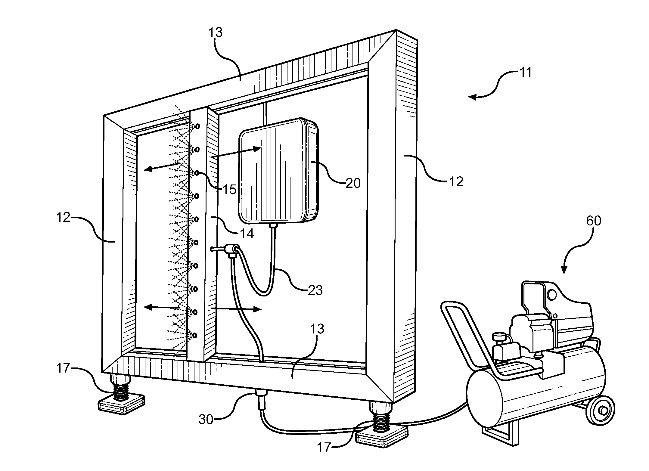
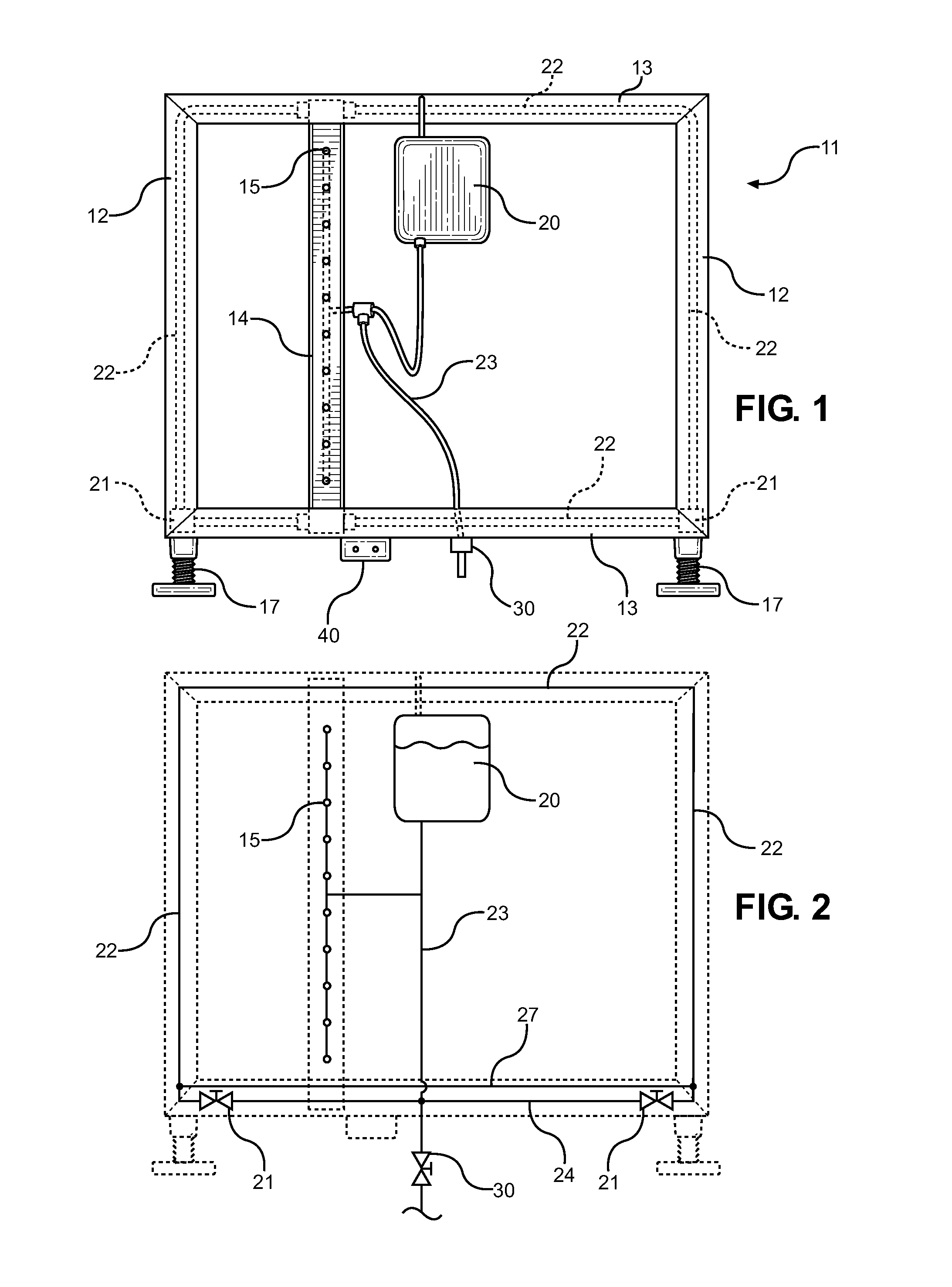
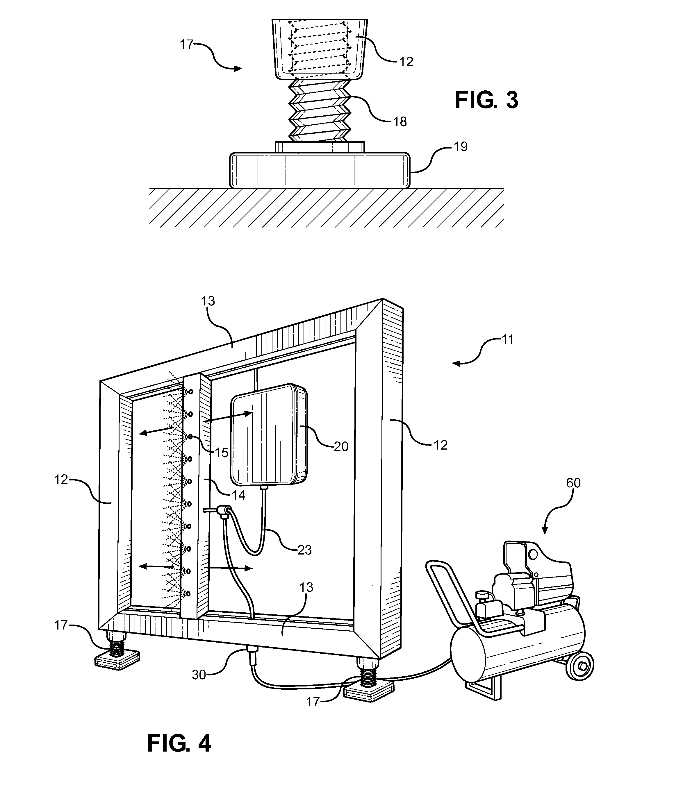
[0030]Reference is made herein to the attached drawings. Like reference numerals are used throughout the drawings to depict like or similar elements of the pneumatic painting device. For the purposes of presenting a brief and clear description of the present invention, the preferred embodiment will be discussed as used for painting large, exposed surfaces with a uniform coating of surface material applied using compressed air. The figures are intended for representative purposes only and should not be considered to be limiting in any respect.

[0031]Referring now to FIG. 1, there is shown a view of the pneumatic painting device of the present invention in a working state. The device comprises a painting frame 11 having a first and second upright frame end member 12 connected to an upper and lower frame member 13, wherein the members form a largely rectangular shape. Within the interior of the rectangular painting frame 11 is a slidable paint rail 14, which is slidable along the length...


PUM


Abstract

A pneumatically controlled painting frame is provided for painting large, open surfaces with a uniform coating of paint, primer, or other surface coating that is spray-applied. The device comprises a rectangular frame having a slidable paint spray rail within the frame. The paint spray rail is slidably controlled using compressed air, which forces the rail along the frame in a singular direction, while the compressed air draws the coating from a container for communication through a plurality of spray nozzles along one surface of the rail. The device is positioned against a surface, adjusted using jack screw base supports, connected to a compressor, and operated using a remote control, which activates the release of the compressed air through the system to allow one pass of the rail across the adjacent surface for coating the same.

Description

BACKGROUND OF THE INVENTION[0001]1. Field of the Invention[0002]The present invention relates to painting tools and paint spraying devices. More specifically, the present invention pertains to a paint spray frame that utilizes compressed air to control a spray rail that is slidably positioned within the frame. The assembly allows a user to paint an enlarged surface without using an individual sprayer, brush, or roller, while also not personally handling the same.[0003]Painting large surfaces or large swaths of interior spaces can be quite labor intensive and require considerable time to accomplish. Generally painting contractors or individual homeowners will utilize paint rollers or paint sprayers and manually apply the paint using the tool. The user directs the paint onto the wall, covering the entire portion desired to be painted, and then makes more passes if more than one coating of paint is required. While this procedure is well known and is effective for painting interior and ...

Claims


Application Information

Patent Timeline
Patent Type & Authority Applications(United States)
IPC IPC(8): B05B3/18
CPCB05B3/18B05B3/14B05B13/005B05B13/041B05B15/55B05B15/68
Inventor BELLAMY, JOSEPH
Owner BELLAMY JOSEPH
Learn More