Structured illumination microscopy optical arrangement including projection artifact supression element

Active Publication Date: 2015-05-21
MITUTOYO CORP
View PDF1 Cites 23 Cited by
  • Summary
  • Abstract
  • Description
  • Claims
  • Application Information

AI Technical Summary

Benefits of technology

[0005]This summary is provided to introduce a selection of concepts in a simplified form that are further described below in the Detailed Description. This summary i

Problems solved by technology

This is particularly challenging with regard to Z-height measurements.
Determining a best focus position is a relatively complex process that generally depends on combining and/or comparing information derived from multiple images.
However, the systems and methods used in known structured illumination pattern (SIP) generating subsystems (e.g., for forming and shifting the patterns) have so far limited the economy, versatility, and/or resolution and accuracy improvements of practical SIM systems in und

Method used


Image

  • Structured illumination microscopy optical arrangement including projection artifact supression element
  • Structured illumination microscopy optical arrangement including projection artifact supression element
  • Structured illumination microscopy optical arrangement including projection artifact supression element

Examples


Embodiment Construction

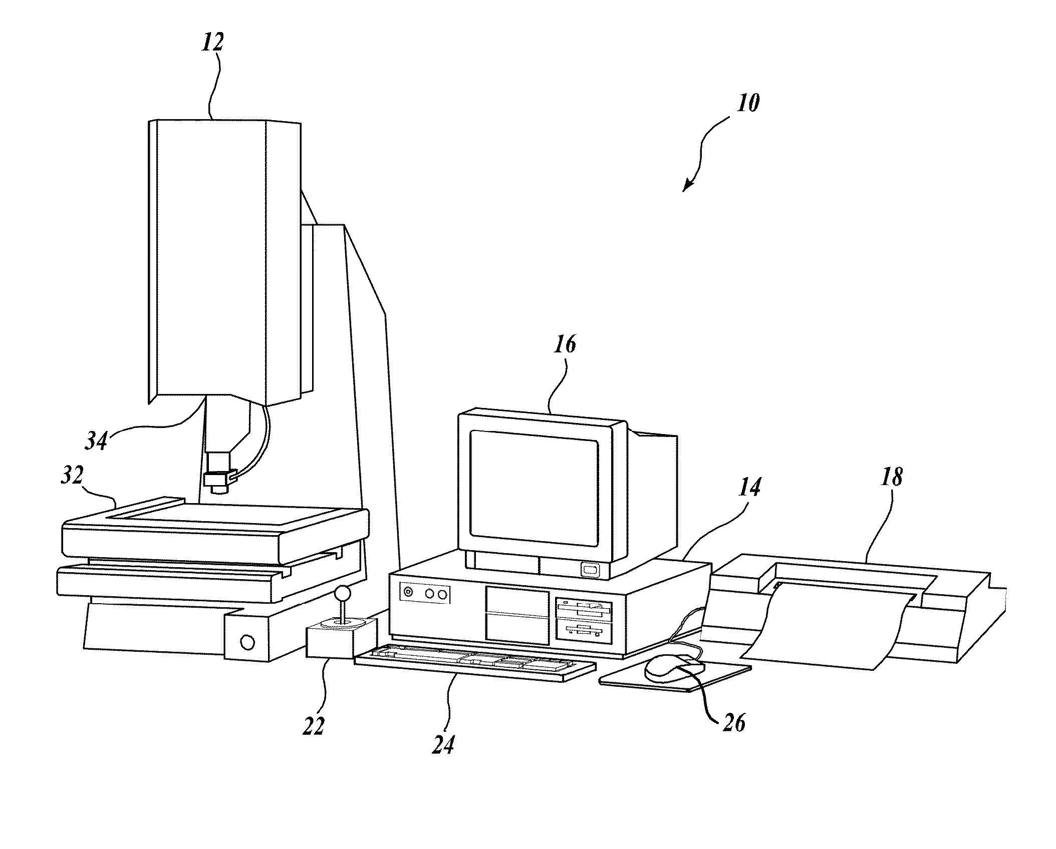
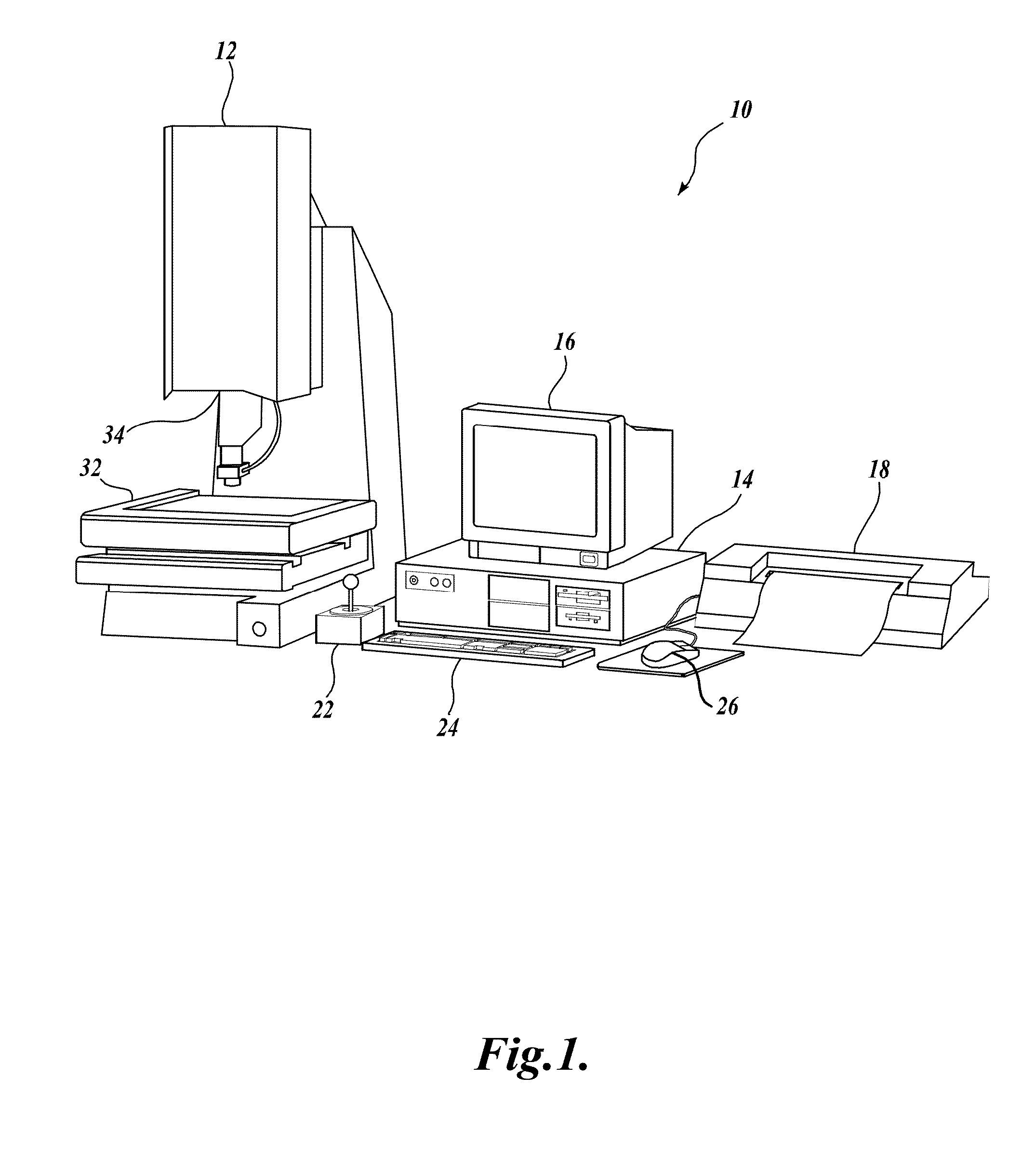
[0021]FIG. 1 is a block diagram showing various typical components of one exemplary precision machine vision inspection system 10 usable in accordance with configurations and methods described herein. The machine vision inspection system 10 includes a vision components portion 12 that is operably connected to exchange data and control signals with a controlling computer system 14. The controlling computer system 14 is further operably connected to exchange data and control signals with a monitor or display 16, a printer 18, a joystick 22, a keyboard 24, and a mouse 26. The monitor or display 16 may display a user interface suitable for controlling and / or programming the operations of the machine vision inspection system 10. It will be appreciated that in various embodiments, a touchscreen tablet or the like may be substituted for and / or redundantly provide the functions of any or all of the computer system 14, the display 16, the joystick 22, the keyboard 24, and the mouse 26.

[0022]...


PUM


Abstract

A structured illumination microscopy optical arrangement includes a projection path and an imaging path. The imaging path includes an imaging sensor and imaging optical elements. The projection path includes a light generator, a pattern generating element such as a spatial light modulator (SLM), and projection optical elements including an output lens and a projector artifact suppression element (PASE) located in the projection path between the SLM and the output lens. The PASE may include birefringent material which splits respective light rays of the structured illumination pattern source light to provide at least one replication of the structured illumination pattern with an offset transverse to the projection path. The offset replication of the structured illumination pattern increases the accuracy of the system by reducing spatial harmonic errors and spurious intensity variations due to projector pixel gap artifacts which may otherwise produce errors in resulting Z-height measurements.

Description

TECHNICAL FIELD[0001]The invention relates generally to metrology systems, and more particularly to systems utilizing structured illumination microscopy methods to obtain measurements of inspected objects.BACKGROUND[0002]Precision machine vision inspection systems (or “vision systems” for short) can be utilized to obtain precise dimensional measurements of inspected objects and to inspect various other object characteristics. Such systems may include a computer, a camera and optical system, and a precision stage that is movable in multiple directions to allow workpiece inspection. One exemplary prior art system, that can be characterized as a general-purpose “off-line” precision vision system, is the commercially available QUICK VISION® series of PC-based vision systems and QVPAK® software available from Mitutoyo America Corporation (MAC), located in Aurora, Ill. The features and operation of the QUICK VISION® series of vision systems and the QVPAK® software are generally described,...

Claims


Application Information

Patent Timeline
IPC IPC(8): G02B21/36G02B21/06
CPCG02B21/06G02B21/361G02B21/0016G02B21/082G02B21/367G01B11/25H04N23/70
Inventor DE NOOIJ, FRANSGLADNICK, PAUL GERARD
Owner MITUTOYO CORP
Why Eureka
Try Eureka