Organic light-emitting display apparatus

a display apparatus and light-emitting technology, applied in the field of display apparatuses, can solve the problems of easy deterioration of the intermediate layer between the pixel electrode and the opposite electrode, insufficient front brightness of the organic light-emitting display apparatus, etc., and achieve the effect of reducing color variation and increasing brightness

a display apparatus and light-emitting technology, applied in the field of display apparatuses, can solve the problems of easy deterioration of the intermediate layer between the pixel electrode and the opposite electrode, insufficient front brightness of the organic light-emitting display apparatus, etc., and achieve the effect of reducing color variation and increasing brightness

US20150137082A1Active Publication Date: 2015-05-21SAMSUNG DISPLAY CO LTD

Image

  • Organic light-emitting display apparatus
  • Organic light-emitting display apparatus
  • Organic light-emitting display apparatus

Examples


Embodiment Construction

[0019]Since the present invention may have various modifications and several embodiments, exemplary embodiments are shown in the drawings and will be described in detail. Advantages, features, and a method of achieving the same will be specified with reference to embodiments described below in detail together with the attached drawings. However, the embodiments may have different forms and should not be construed as being limited to the descriptions set forth herein.

[0020]Hereinafter, the embodiments of the present invention will be described in detail with reference to the attached drawings, in which like reference numerals refer to like elements and a repetitive explanation thereof will be omitted.

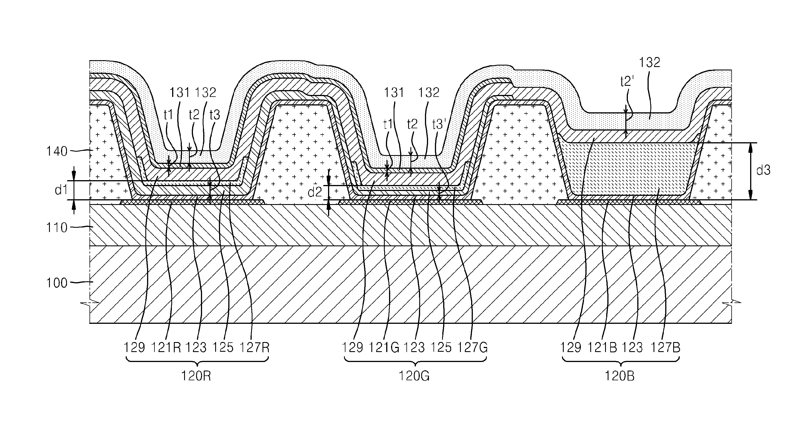
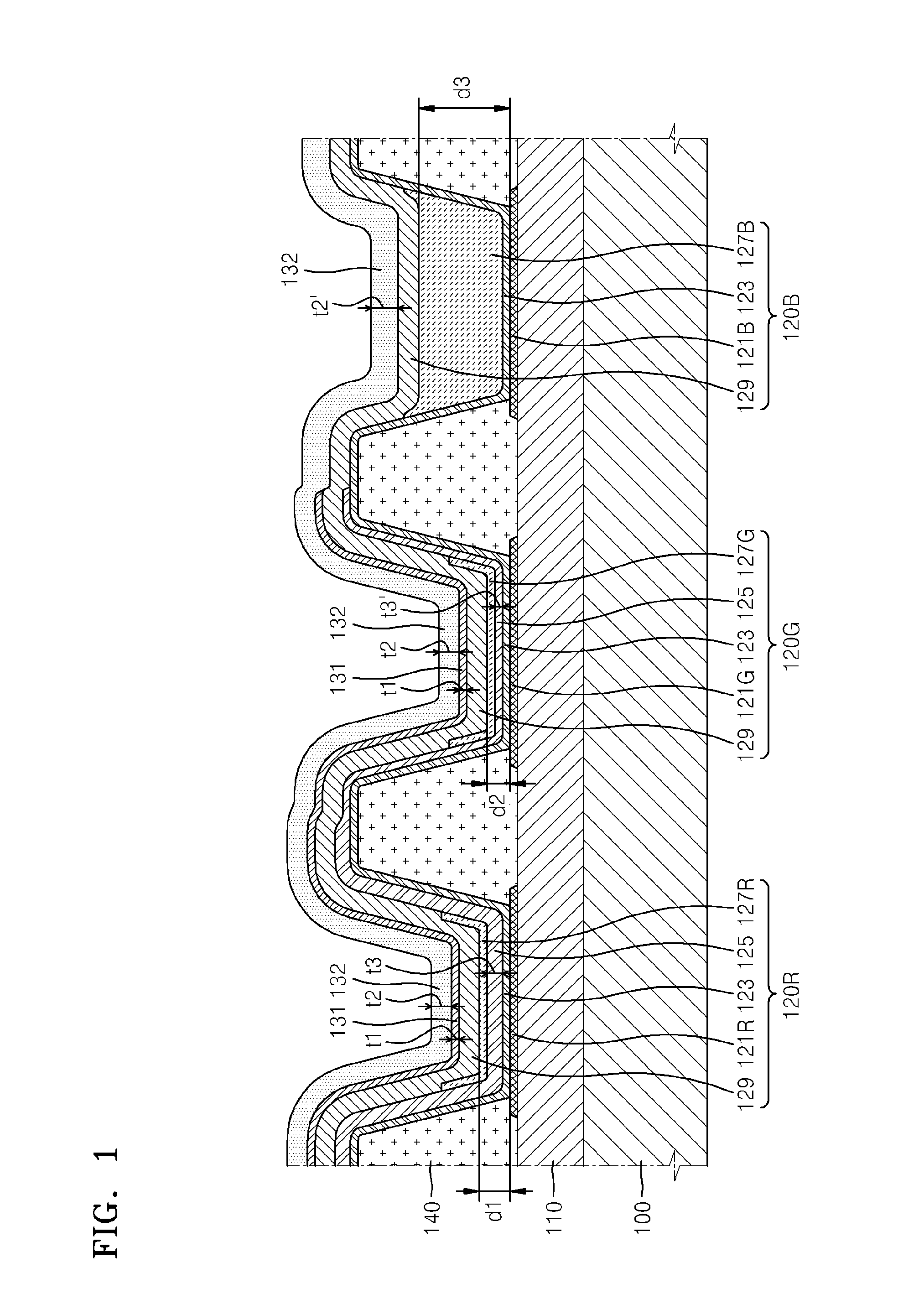
[0021]On the other hand, it will be understood that when a layer, region, or component is referred to as being formed β€œon” another layer, region, or component, it can be directly or indirectly formed on the other layer, region, or component. That is, for example, intervening layers, regi...


PUM


Abstract

Provided is an organic light-emitting display apparatus, including a substrate, a first pixel electrode, a second pixel electrode, and a third pixel electrode, disposed on the substrate separated from one another, a red emission layer disposed corresponding to the first pixel electrode, a green emission layer disposed corresponding to the second pixel electrode, and a blue emission layer disposed corresponding to the third pixel electrode, an opposite electrode disposed over the red, green, and blue emission layers facing the first to third pixel electrodes, a first capping layer disposed on the opposite electrode corresponding to the first and second pixel electrodes, and a second capping layer disposed on the first capping layer corresponding to the first and second pixel electrodes and disposed on the opposite electrode to correspond to the third pixel electrode.

Description

CROSS REFERENCE TO RELATED APPLICATION[0001]This application claims priority from and the benefit of Korean Patent Application No. 10-2013-0140893, filed on Nov. 19, 2013 which is hereby incorporated by the reference for all purposes as if fully set forth herein.BACKGROUND[0002]1. Field[0003]Exemplary embodiments of the present invention relate to a display apparatus, and more particularly, to an organic light-emitting display apparatus.[0004]2. Discussion of the Background[0005]Organic light-emitting display apparatuses each include an organic light-emitting device (OLED) as a pixel, and the OLED includes a pixel electrode and an opposite electrode facing each other, and an intermediate layer disposed therebetween having an emission layer. Light generated by the emission layer is emitted outward and observed by a user. However, all the light generated by the emission layer is not emitted outward. In other words, some of the light generated by the emission layer is guided along the ...

Claims


Application Information

Patent Timeline
21 May 2015
Publication
US20150137082A1
IPC
H01L27/32; H01L51/52
CPC
H01L51/5203; H01L27/3211; H10K59/35; H10K2102/3026; H10K2102/351; H10K59/876; H10K59/873; H10K59/80518
Inventors
KIM, JAE-KYOUNG; KIM, GEE-BUM