First Embodiment
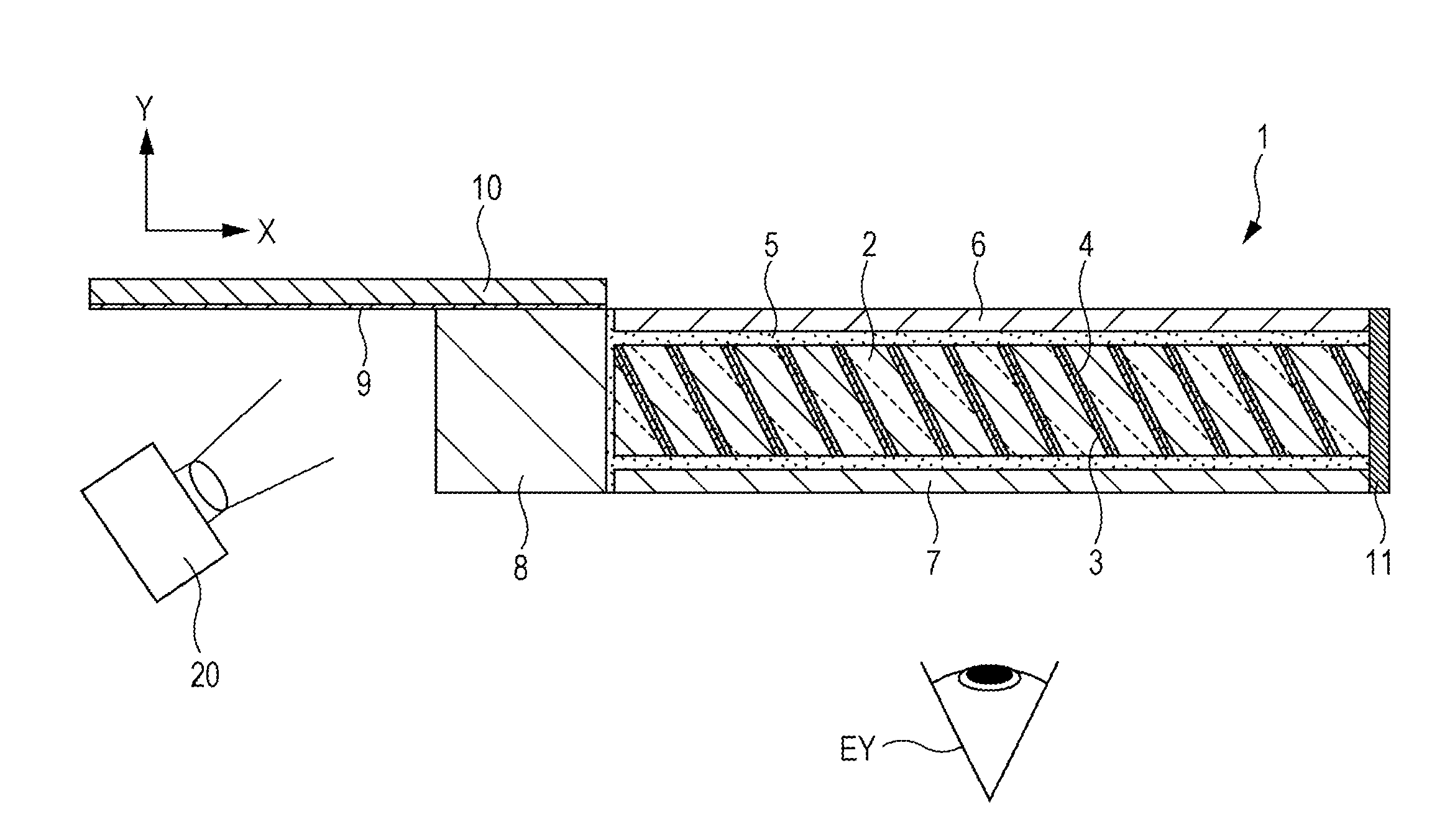
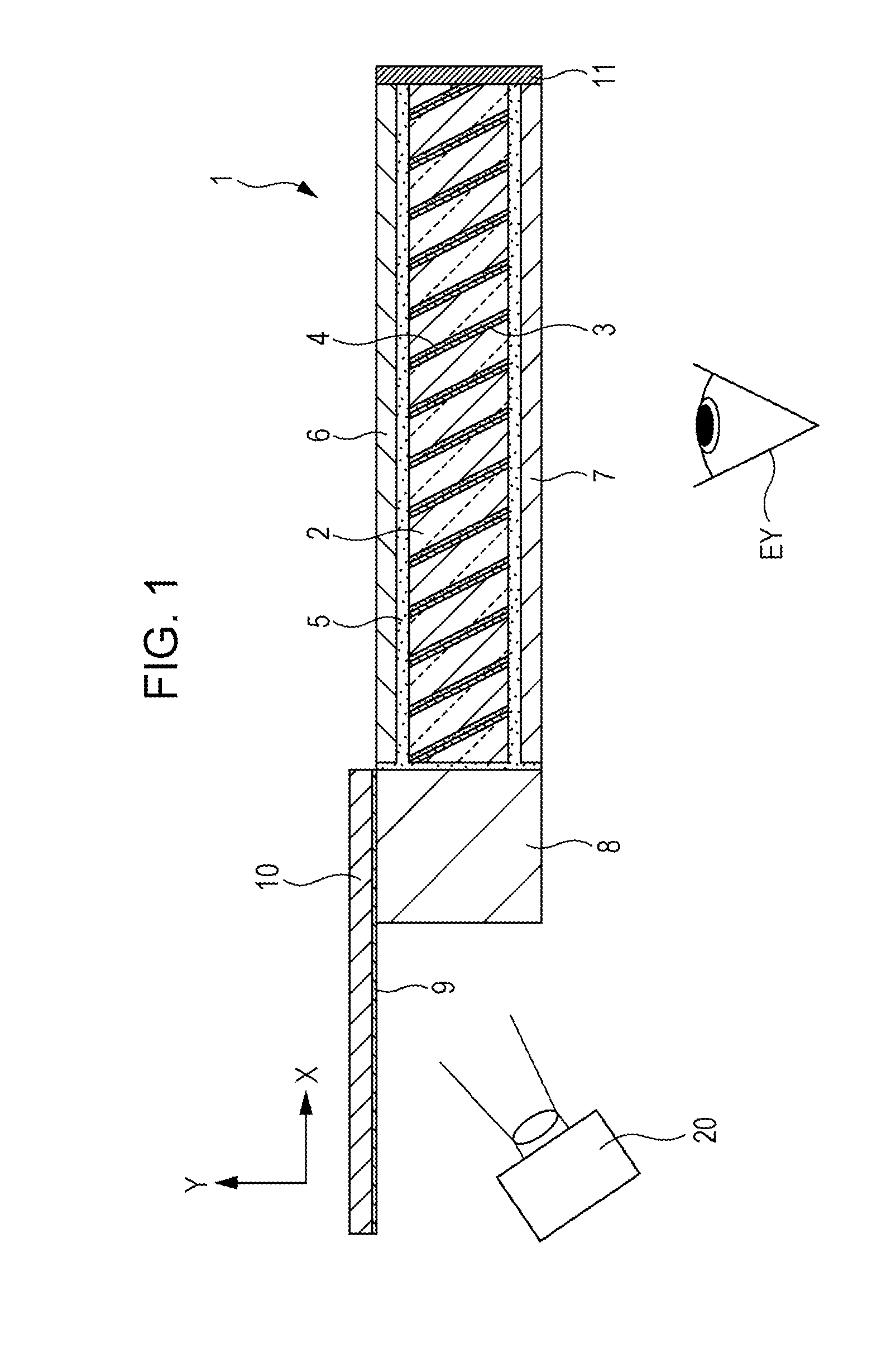
[0031]FIG. 1 is a side view illustrating the whole image of an optical device 1 according to the first embodiment. As illustrated in FIG. 1, the optical device 1 includes a light guide plate 2, an upper flat plate 6, a lower flat plate 7, an introduction block 8, an incident light intake mirror 9, and a mirror supporting plate 10.
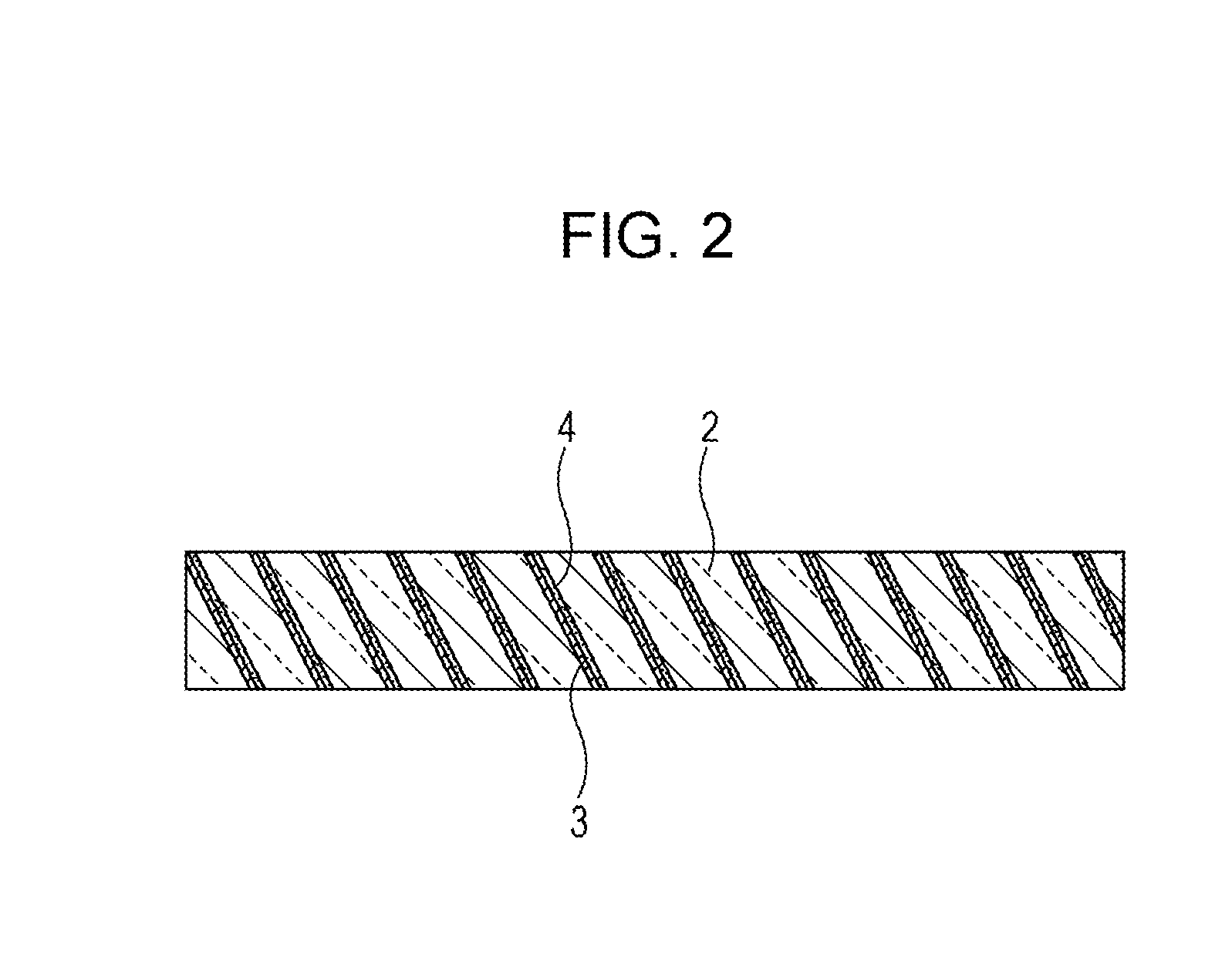
[0032]As illustrated in FIG. 2, the light guide plate 2 is created by (i) forming a transflective layer 3 on plate-like members made of a material such as a light transmissive resin material by a method such as vapor deposition, (ii) bonding, with an adhesive 4, such plate-like members on which the transflective layer 3 has been formed so that the plate-like members are shifted from each other in accordance with an inclination angle, and (iii) cutting the plate-like members thus bonded.
[0033]The light guide plate 2 is bonded to the upper flat plate 6 and the lower flat plate 7 with an adhesive 5, and the upper flat plate 6 and the lower flat plate 7 are kept parallel with each other by pressing. The refractive index of the adhesive 5 is set to a refractive index the same as or close to that of the light guide plate 2.
[0034]The upper flat plate 6 is a plate-like member made of a material such as a light transmissive resin material. Assume that the Y direction in FIG. 1 is an upward direction, at least a topmost surface of the upper flat plate 6 is flat. The refractive index of the upper flat plate 6 is set to a refractive index different from that of the adhesive 5 and the light guide plate 2. As described above, the upper flat plate 6 and the lower flat plate 7 are kept parallel with each other by pressing. Furthermore, the upper flat plate 6 is desirably formed so that a surface thereof that is bonded to the introduction block 8 is flat. It should be noted that, instead of using the adhesive 5, such an arrangement is also possible in which the light guide plate 2 is sandwiched between the upper flat plate 6 and the lower flat plate 7 and a gap between the light guide plate 2 and the upper flat plate 6 and a gap between the light guide plate 2 and the lower flat plate 7 are filled with a resin. In this case, the refractive index of the resin 5 is set to a refractive index the same as or close to that of the light guide plate 2.
[0035]The lower flat plate 7 is a plate-like member made of a material such as a light transmissive resin material. Assume that the Y direction in FIG. 1 is an upward direction, a bottommost surface of the lower flat plate 7 is flat. The refractive index of the lower flat plate 7 is set to the same refractive index as the upper flat plate 6. As described above, the upper flat plate 6 and the lower flat plate 7 are kept parallel with each other by pressing. Furthermore, the lower flat plate 7 is desirably formed so that a surface thereof that is bonded to the introduction block 8 is flat.
[0036]The introduction block 8 is a member made of a material such as a light transmissive resin material, and at least opposing surfaces of the introduction block 8 are parallel with each other. The height of the introduction block 8 in the Y direction of FIG. 1 is equal to a distance in the Y direction from the topmost surface of the upper flat plate 6 to the bottommost surface of the lower flat plate 7. The upper flat plate 6 and the lower flat plate 7 are connected to the introduction block 8 at right angles.
[0037]The incident light intake mirror 9 is bonded onto the mirror supporting plate 10 made of a material such as a light transmissive resin material. Assume that the Y direction in FIG. 1 is an upward direction, an end of the incident light intake mirror 9 is attached to the top surface of the introduction block 8.
[0038]A light blocking layer 11 made of, for example, a black coating material is provided on ends, in the X direction in FIG. 1, of the upper flat plate 6, the lower flat plate 7, and the light guide plate 2.
[0039]In the optical device 1 described above, when image light is projected from an image display source 20, the image light is reflected by the incident light intake mirror 9 and is then guided to the light guide plate 2 by the introduction block 8. Part of the light guided to the light guide plate 2 is reflected by the transflective layer 3 and then reaches the eyes EY of a viewer. Part of the reflected light travels inside the light guide plate 2 while being reflected by the upper flat plate 6 and the lower flat plate 7. Furthermore, light that was not reflected by the transflective layer 3 also travels inside the light guide plate 2 while being reflected by the upper flat plate 6 and the lower flat plate 7. At least the topmost surface of the upper flat plate 6 and the bottommost surface of the lower flat plate 7 are flat and are kept parallel with each other. Therefore, light reflected by the upper flat plate 6 and the lower flat plate 7 is guided in a state in which total reflection conditions are satisfied. As a result, there is no loss of light.
[0040]As described above, the light guide plate 2 is created by (i) forming the transflective layer 3 on a plate-like member made of a material such as a light transmissive resin material by a method such as vapor deposition, (ii) bonding, with the adhesive 4, such plate-like members on which the transflective layer 3 has been formed so that the plate-like members are shifted from each other in accordance with an inclination angle, and (iii) cutting the plate-like members thus bonded. It is therefore difficult to achieve flatness of the top surface and the bottom surface of the light guide plate 2 and to keep the top surface and the bottom surface of the light guide plate 2 parallel with each other.
[0041]However, the light guide plate 2 according to the present embodiment is bonded to the upper flat plate 6, which is formed so that at least the topmost surface is flat, and the lower flat plate 7, which is formed so that at least the bottommost surface is flat, with the adhesive 5. Furthermore, at least the topmost surface of the upper flat plate 6 and the bottommost surface of the lower flat plate 7 are kept parallel with each other by pressing.
[0042]Therefore, even in the case of using the light guide plate 2 having a multilayer structure, in a case where the upper flat plate 6, the lower flat plate 7, and the light guide plate 2 are considered a monolithic light guide plate, it is possible to secure flatness of the top surface and the bottom surface of the light guide plate and to keep the top surface and the bottom surface parallel with each other well. The flatness just needs to be the same degree of flatness as that of a flat plate member used in the formation of the light guide plate 2.
[0043]Furthermore, the gap between the upper flat plate 6 and the light guide plate 2 and the gap between the lower flat plate 7 and the light guide plate 2 are filled with the adhesive 5. Therefore, even in a case where the transflective layer 3 is exposed in the process of creating the light guide plate 2 having a multilayer structure, it is possible to prevent degradation of the transflective layer 3 since the transflective layer 3 is covered with the adhesive 5.
[0044]Furthermore, in the present embodiment, the light blocking layer 11 is provided on the ends. This makes it possible to block external light with certainty. As a result, there is no possibility that an image is hard to see.
[0045]As described above, according to the present embodiment, it is possible to provide an optical element that is capable of displaying a virtual image well while solving the problems of a light guide plate having a multilayer structure.