Image processing apparatus and method

Active Publication Date: 2015-05-21
SONY CORP
View PDF2 Cites 13 Cited by
  • Summary
  • Abstract
  • Description
  • Claims
  • Application Information

AI Technical Summary

Benefits of technology

[0034]According to the present disclosure, it is possible to decode an image. In par

Problems solved by technology

The MPEG2 has been mainly used for high image quality encoding suitable for broadcasting, but has not been compatible wi

Method used


Image

  • Image processing apparatus and method
  • Image processing apparatus and method
  • Image processing apparatus and method

Examples


first embodiment

1. First Embodiment

[0090][Image Encoding Device]

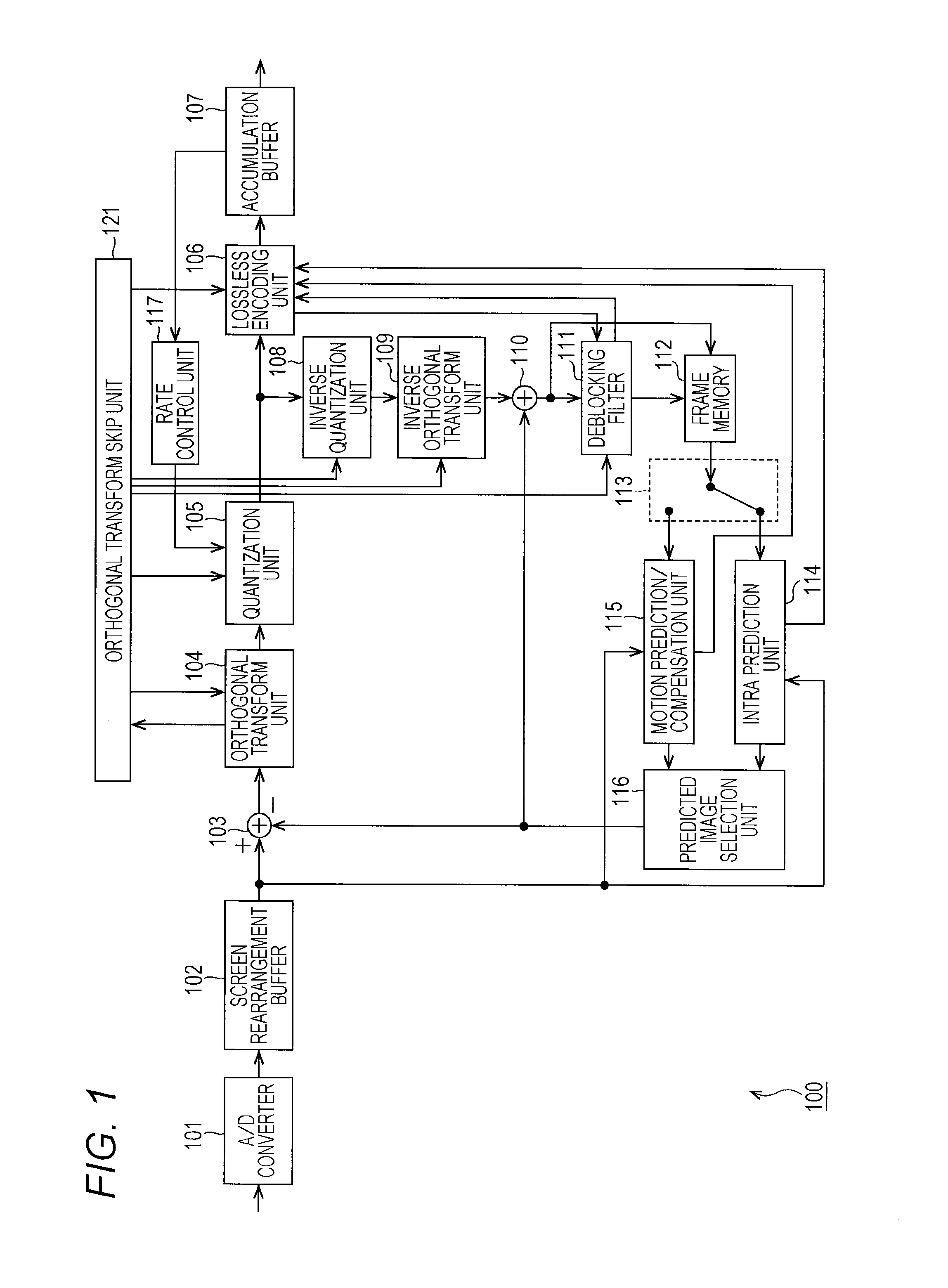
[0091]FIG. 1 is a block diagram illustrating an example of a main configuration of an image encoding device.

[0092]An image encoding device 100 illustrated in FIG. 1 encodes image data using prediction processing of, for example, high efficiency video coding (HEVC) or a system that is compliant therewith.

[0093]As illustrated in FIG. 1, the image encoding device 100 includes an A / D converter 101, a screen rearrangement buffer 102, a computation unit 103, an orthogonal transform unit 104, a quantization unit 105, a lossless encoding unit 106, an accumulation buffer 107, an inverse quantization unit 108, and an inverse orthogonal transform unit 109. In addition, the image encoding device 100 includes a computation unit 110, a deblocking filter 111, a frame memory 112, a selection unit 113, an intra prediction unit 114, a motion prediction / compensation unit 115, a predicted image selection unit 116, and a rate control unit 117.

[0094]The ima...

second embodiment

2. Second Embodiment

[0274][Image Decoding Device]

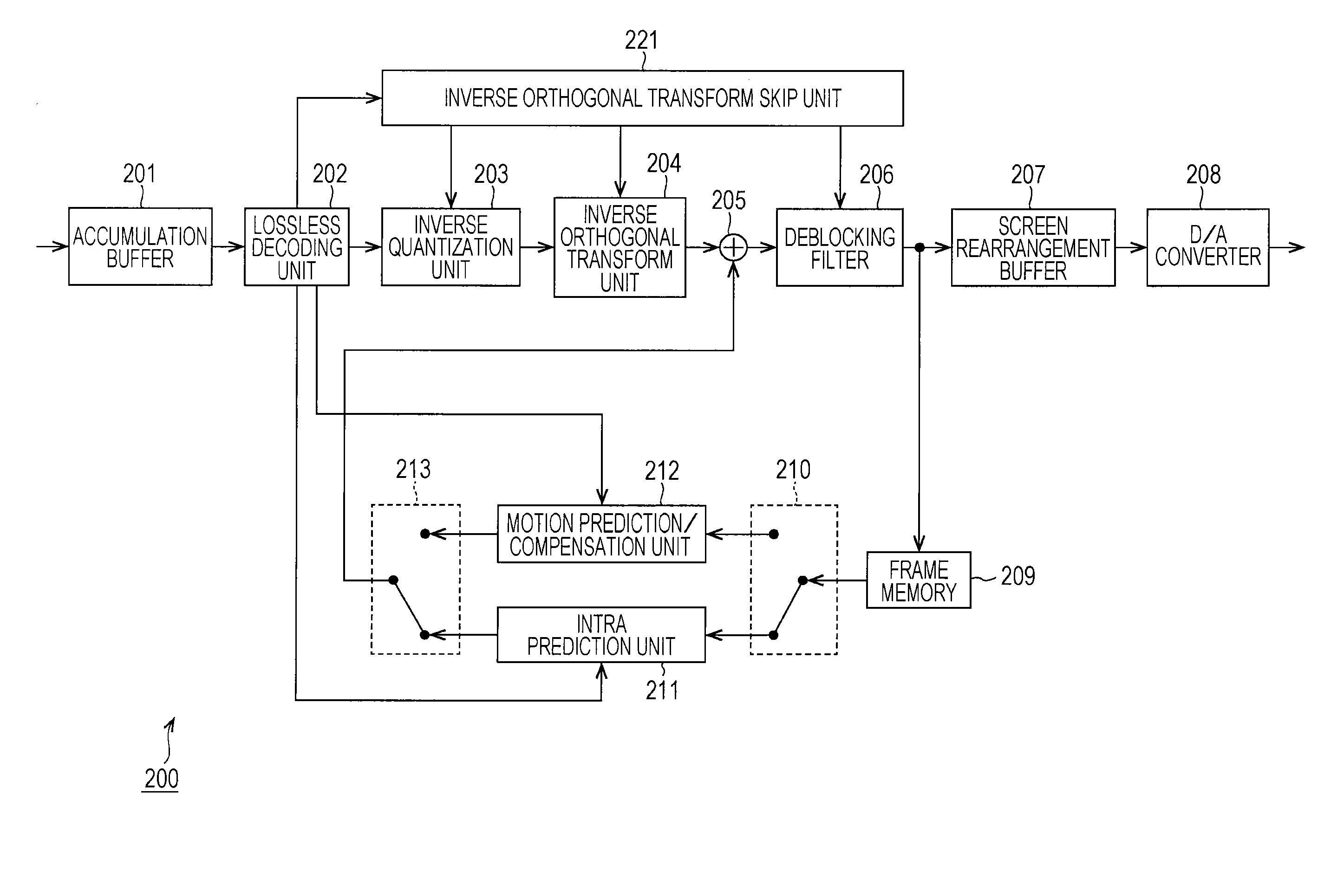
[0275]Next, decoding of the coded data (a coded stream) which is encoded as described above will be described. FIG. 19 is a block diagram illustrating an example of a main configuration of an image decoding device corresponding to the image encoding device 100 in FIG. 1.

[0276]An image decoding device 200 illustrated in FIG. 19 decodes the coded data generated by the image encoding device 100, using a decoding method corresponding to the coding system thereof.

[0277]As illustrated in FIG. 19, the image decoding device 200 includes an accumulation buffer 201, a lossless decoding unit 202, an inverse quantization unit 203, an inverse orthogonal transform unit 204, a computation unit 205, a deblocking filter 206, a screen rearrangement buffer 207, and a D / A converter 208. In addition, the image decoding device 200 includes a frame memory 209, a selection unit 210, an intra prediction unit 211, a motion prediction / compensation unit 212, and...

third embodiment

3. Third Embodiment

[0362][Transmission Control of Skip Enable Information]

[0363]However, as described above, the orthogonal transform skip can be applied to 4×4 luminance orthogonal transform block (TU of luminance component) or 4×4 chrominance orthogonal transform block (TU of chrominance component).

[0364]On the contrary, for example, a minimum size of the TU is designated by syntax which is referred to as log 2_min_transform_block_size_minus2 in the HEVC or the like. For example, in the sequence parameter set (SPS) illustrated in FIG. 4, the minimum size of the TU is designated by the log 2_min_transform_block_size_minus2 indicated in the sixth row from the bottom.

[0365]When the minimum size designated by the log 2_min_transform_block_size_minus2 is larger than 4×4, the 4×4 orthogonal transform block (TU) is not present. That is, in this case, there is no possibility that the orthogonal transform skip (TransformSkip) is applied. Accordingly, there is no need to transmit the skip e...


PUM


Abstract

The present disclosure relates to an image processing device and a method capable of suppressing the reduction of an image quality due to encoding/decoding. The image processing device includes: a quantization unit that when orthogonal transform processing is skipped with respect to a current block, quantizes all components of the current block using one weighting coefficient and when the orthogonal transform processing is performed on the current block, quantizes each component of the current block using a quantization matrix; an encoding unit that encodes the coefficient of the current block which is quantized by the quantization unit; and a transmission unit that transmits the coded data of the current block which is obtained by being encoded by the encoding unit. The present disclosure can be applied to, for example, an image processing device.

Description

TECHNICAL FIELD[0001]The present disclosure relates to an image processing device and method, and more particularly relates to an image processing device and method capable of suppressing image deterioration.BACKGROUND ART[0002]In recent years, devices have come into widely use in which an image is subjected to compression encoding by employing a coding system by handling image information as digital, and at this time compressing the image by orthogonal transform, such as discrete cosine transform or the like, and motion compensation, taking advantage of redundancy which is a feature of the image information, in order to perform highly efficient transmission and storage of information. Examples of this coding system include a Moving Picture Experts Group (MPEG) and so forth.[0003]In particular, MPEG2 (ISO / IEC 13818-2) is defined as a general-purpose image coding system, and is a standard that covers both interlaced scanning images and progressive scanning images as well as standard-...

Claims


Application Information

Patent Timeline
IPC IPC(8): H04N19/124H04N19/176H04N19/157
CPCH04N19/124H04N19/176H04N19/157H04N19/12H04N19/70H04N19/103H04N19/44H04N19/60
Inventor SATO, KAZUSHIMORIGAMI, YOSHITAKALU, SHUO
Owner SONY CORP
Why Eureka
Try Eureka