Apparatus and method of transmitting data in multi-carrier system

Inactive Publication Date: 2015-05-21
ELECTRONICS & TELECOMM RES INST
7 Cites 13 Cited by

AI-Extracted Technical Summary

Problems solved by technology

However, if there is a lot of additional data of little importance in transmi...

Benefits of technology

[0017]The selecting may include selecting a pulse-shaping filter having a longer pulse-shaping period for data of higher priority.
[...

Abstract

An apparatus of transmitting data in a multi-carrier system includes: a plurality of pulse-shaping filters for performing pulse shaping of incoming data symbols during a set pulse-shaping period; and a plurality of frequency converters convert signals that are pulse-shaped by the plurality of pulse-shaping filters into signals with frequency bands for a plurality of subcarriers.

Application Domain

Technology Topic

Image

  • Apparatus and method of transmitting data in multi-carrier system
  • Apparatus and method of transmitting data in multi-carrier system
  • Apparatus and method of transmitting data in multi-carrier system

Examples

  • Experimental program(1)

Example

[0027]In the following detailed description, only certain exemplary embodiments of the present invention have been shown and described, simply by way of illustration. As those skilled in the art would realize, the described embodiments may be modified in various different ways, all without departing from the spirit or scope of the present invention. Parts irrelevant to the description are omitted to clearly describe the present invention, and like reference numerals denote like elements throughout the drawings.
[0028]In the specification, when a certain part “includes” a certain component, this indicates that the part may further include another component instead of excluding another component unless there is a different disclosure.
[0029]Now, an apparatus and method of transmitting data in a multi-carrier system according to an exemplary embodiment of the present invention will be described in detail with reference to the drawings.
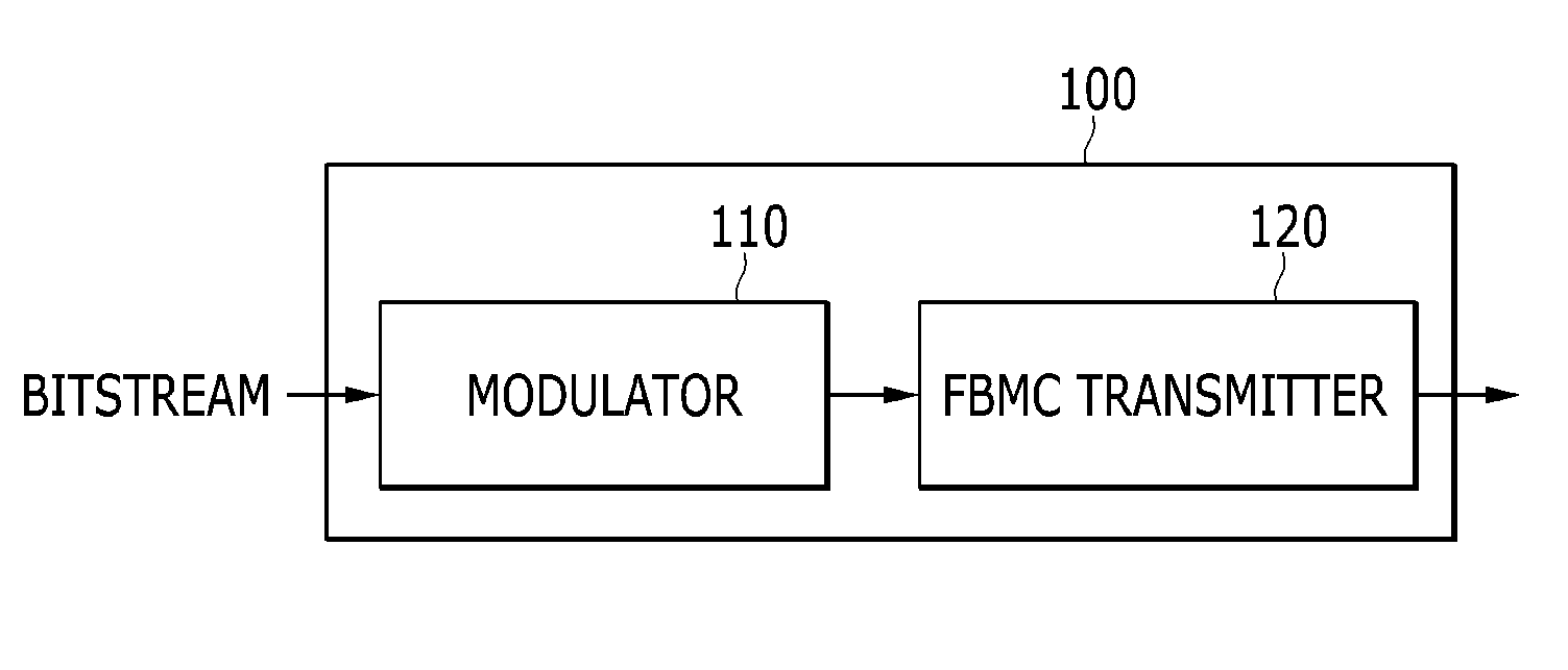
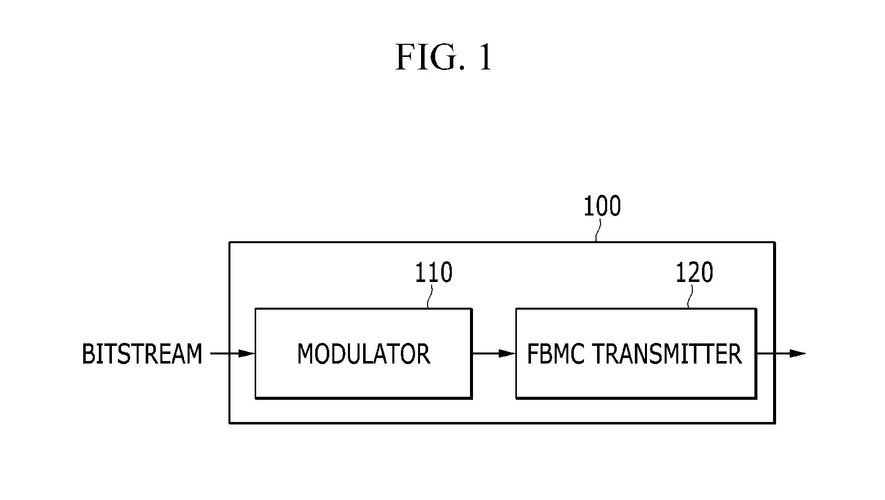
[0030]FIG. 1 is a view showing schematically showing an apparatus of transmitting data in a multi-carrier system according to an exemplary embodiment of the present invention, and FIG. 2 is a view showing an FBMC transmitter of FIG. 1. FIG. 3 is a flowchart showing a method of transmitting data in a multi-carrier system according to an exemplary embodiment of the present invention.
[0031]Referring to FIG. 1, a data transmitting apparatus 100 in a multi-carrier system includes a modulator 110 and an FBMC (filter bank multi-carrier) transmitter 120.
[0032]Referring to FIG. 3, the modulator 110 modulates an incoming bitstream (S310). The modulator 110 can modulate a bitstream input by a transmission scheme such as BPSK (binary phase shift keying), QPSK (quadrature phase shift keying), or QAM (quadrature amplitude modulation) into data symbols.
[0033]Referring to FIG. 2, the FBMC transmitter 120 includes a filter selector 122, a transmission filter bank 124, and a coupler 126.
[0034]Referring to FIG. 2 and FIG. 3, the filter selector 122 selects a pulse-shaping filter to be applied to data symbols input from the modulator 110 (S320), and transmits the data symbols to the one selected from among the plurality of pulse-shaping filters 12411 to 1241N. For example, if priority is set on an incoming bitstream, the filter selector 122 can select the pulse-shaping filter to be applied to the data symbols according to priority. Also, the filter selector 122 can select the pulse-shaping filter to be applied to the data symbols according to the importance of the incoming bitstream.
[0035]The transmission filter bank 124 performs pulse shaping of incoming data symbols and transmits them by a plurality of multi-carriers. The transmission filter bank 124 includes the plurality of pulse-shaping filters 12411 to 1241N and a plurality of frequency converters 12421 to 1242N.
[0036]The number of pulse-shaping filters 12411 to 1241N corresponds to the number of multi-carriers used. The pulse-shaping filters 12411 to 1241N have an impulse response PT(t), and perform pulse shaping of data symbols at a symbol response speed set according to the impulse response PT(t) and outputs them to the corresponding frequency converters 12421 to 1242N (S330).
[0037]The pulse-shaping filters 12411 to 1241N according to the exemplary embodiment of the present invention each have a different pulse-shaping period (=τ*Ts). Ts is the symbol transmission period which allows for transmission without causing inter-symbol interference, and τ is an FTN (faster than Nyquist) transmission parameter which has a value between 0 and 1 (0≧τ≧1).
[0038]That is, the pulse-shaping filters 12411 to 1241N according to the exemplary embodiment of the present invention have different τ values, and at least one of the pulse-shaping filters 12411 to 1241N has a pulse-shaping period which satisfies the τ value of 1, that is, the Nyquist's condition, and the other pulse-shaping filters have a τ value of less than 1. Signal transmission through a pulse-shaping filter having a τ value of less than 1 is referred to as FTN transmission.
[0039]Signals transmitted through a pulse-shaping filter having a large τ value are less affected by channels. Instead, the amount of data transmitted through a pulse-shaping filter having a large τ value becomes relatively smaller. On the other hand, the pulse-shaping period becomes shorter as the τ value becomes smaller. Hence, the amount of data transmitted through a pulse-shaping filter having a small τ value becomes relatively larger. However, the smaller the τ value, the greater the inter-symbol interference (ISI) of a transmission signal. This increases signal deterioration.
[0040]Accordingly, the filter selector 122 selects a pulse-shaping filter having a larger τ value for data of higher priority or importance. For example, data of very high priority or importance, which should be necessarily transmitted, can be transmitted through a pulse-shaping filter having the τ value of 1. Also, data of lower priority or importance can be transmitted through a pulse-shaping filter having a smaller τ value.
[0041]Next, the pulse-shaping filters 12411 to 1241N convert pulse-shaped signals into signals with frequency bands occupied by a plurality of subcarriers and output them (S340).
[0042]The coupler 126 couples the signals with the frequency bands of the plurality of subcarriers and outputs them through an antenna (S350).
[0043]FIG. 4 is a view showing an example of frequency bands for different subcarriers used in the exemplary embodiment of the present invention.
[0044]As shown in FIG. 4, N subcarriers each have different frequency bandwidths [H0(f), . . . , HN−1(f)]. H0(f), H1(f), . . . , HN−1(f) denote the frequency bandwidth of the N subcarriers at frequencies f0, f1, . . . , fN−1.
[0045]The plurality of frequency converters 12421 to 1242N can convert pulse-shaped signals into signals with the frequency bands [H0(f), H1(f), . . . , HN−1(f)] of the subcarriers by multiplying the pulse-shaped signals by subcarrier signals ej2πƒ 0 t, ej2πƒ 1 t, . . . , ej2πƒ N−1 t.
[0046]FIG. 5 and FIG. 6 are views showing an example of waveforms output from a pulse-shaping filter according to an exemplary embodiment of the present invention. FIG. 7 is a view showing an example of a transmission signal using a pulse-shaping filter having a τ value of less than 1.
[0047]FIG. 5 depicts waveforms output from a pulse-shaping filter having the τ value of 1. From the waveforms output from the pulse-shaping filter having the τ value of 1, it is found out that there is no inter-symbol interference at all.
[0048]FIG. 6 depicts waveforms output from a pulse-shaping filter having a τ value of less than 1. As shown in FIG. 6, it is found out that, although the pulse-shaping filter having a τ value less than 1 can increase the symbol transmission rate compared to FIG. 5, a transmission signal inevitably has inter-symbol interference (ISI).
[0049]Particularly, as shown in FIG. 7, assuming that the transmission signal is [1, −1, 1, −1, −1], the actual transmission signal that has passed through the pulse-shaping filter having a τ value of less than 1 does not have the value of [1, −1, 1, −1, −1], but instead becomes a signal obtained by adding the transmission signal and inter-symbol interference.
[0050]Accordingly, the filter selector 122 selects a pulse-shaping filter having a larger τ value for data of higher priority or importance, thereby allowing a receiver to receive data without distortion caused by inter-symbol interference.
[0051]In this way, the data transmitting apparatus 100 is able to provide different transmission capacity and performance efficiency to different subcarriers by setting different τ values for pulse-shaping filters on different subcarriers.
[0052]Moreover, the data receiving apparatus is able to differentially receive data transmitted on different subcarriers depending on the channel environment and to receive data of high priority or importance without distortion even under a poor channel environment. Further, the data receiving apparatus is able to receive even data of low priority or importance transmitted at high transfer rates if the channel status is good.
[0053]FIG. 8 is a view schematically showing a data receiving apparatus in a multi-carrier system according to an exemplary embodiment of the present invention, and FIG. 9 is a view showing a reception filter bank of FIG. 8.
[0054]Referring to FIG. 8, a data receiving apparatus 800 in a multi-carrier system includes an FBMC receiver 810 and a demodulator 820.
[0055]The FBMC receiver 810 includes a reception filter bank 812.
[0056]Referring to FIG. 9, the reception filter bank 812 includes frequency converters 81211 to 8121N and pulse-shaping filters 81221 to 8122N.
[0057]The frequency converters 81211 to 8121N convert a signal received through channels into baseband signals. The frequency converters 81211 to 8121N are able to convert signals received through channels into baseband signals by multiplying the signals by the corresponding subcarrier signals ej2πƒ 0 t, ej2πƒ 1 t, . . . , ej2πƒ N−1 t.
[0058]The pulse-shaping filters 81221 to 8122N are matched filters of the pulse-shaping filters 12411-1241N of the data receiving apparatus 100, and have an impulse response PR(t) and the same τ value as the pulse-shaping filters 12411 to 1241N.
[0059]The baseband signals output from the frequency converters 81211 to 8121N are pulse-shaped according to the impulse response PR(t) at time t=k*τ*Ts (k is a positive integer) to output data symbols on the corresponding subcarriers.
[0060]The pulse-shaping filters 81221 to 8122N perform pulse shaping the baseband signals during a pulse-shaping period, and output data symbols on the corresponding subcarriers.
[0061]The data symbols on the corresponding subcarriers are transmitted to the demodulator 820 after performing channel compensation on the data symbols and removing inter-symbol from the data symbols. The channel compensation and the inter-symbol interference caused by T can be performed by an equalizer (not shown).
[0062]Referring again to FIG. 8, the demodulator 820 demodulates the data symbols output from the pulse-shaping filters 81221 to 8122N to detect the transmitted bits.
[0063]According to an embodiment of the present invention, it is possible to provide a different data transmission capacity for each subcarrier and adjust the overall data traffic by setting a different pulse-shaping period for each pulse-shaping filter by an FBMC scheme.
[0064]Furthermore, various kinds of data can be received depending on the channel environment, even if the channel environment changes with time, as in a mobile broadcasting environment, and basic data can be received even under a poor channel environment.
[0065]An exemplary embodiment of the present invention may not only be embodied through the above-described apparatus and/or method, but may also be embodied through a program that executes a function corresponding to a configuration of the exemplary embodiment of the present invention or through a recording medium on which the program is recorded, and can be easily embodied by a person of ordinary skill in the art from a description of the foregoing exemplary embodiment.
[0066]While this invention has been described in connection with what is presently considered to be practical exemplary embodiments, it is to be understood that the invention is not limited to the disclosed embodiments, but, on the contrary, is intended to cover various modifications and equivalent arrangements included within the spirit and scope of the appended claims.

PUM

no PUM

Description & Claims & Application Information

We can also present the details of the Description, Claims and Application information to help users get a comprehensive understanding of the technical details of the patent, such as background art, summary of invention, brief description of drawings, description of embodiments, and other original content. On the other hand, users can also determine the specific scope of protection of the technology through the list of claims; as well as understand the changes in the life cycle of the technology with the presentation of the patent timeline. Login to view more.

Similar technology patents

Mass spectrometer

ActiveUS20130304394A1High priorityLow priorityTime-of-flight spectrometersMolecular entity identificationChemistryAnalysis data
Owner:SHIMADZU CORP

Classification and recommendation of technical efficacy words

  • Long period
  • High priority

Image pickup system and image pickup method

ActiveUS20140014820A1Long periodTelevision system detailsSolid-state devicesPhysicsExposure period
Owner:OLYMPUS CORP

Control apparatus for fuel injection valve and mehod thereof

ActiveUS20160108847A1Long periodLess fuel injectionElectrical controlMagnetsElectronic control unitPeak value
Owner:TOYOTA JIDOSHA KK
Why Eureka
Try Eureka