
Flexible positioning post

a positioning post and flexible technology, applied in the direction of screws, pins, fastening means, etc., can solve the problems of inconvenient maintenance of electronic devices, inconvenient maintenance, and inconvenient grounding, so as to increase the grounding area of the circuit board, the effect of expanding the grounding area

Inactive Publication Date: 2015-05-21
WISTRON CORP
View PDF6 Cites 12 Cited by
  • Summary
  • Abstract
  • Description
  • Claims
  • Application Information

AI Technical Summary

Benefits of technology

This patent describes a new design for circuit boards that make them easier to assemble and repair. The design uses metal elastic pieces that can be moved by a metal post to detach the circuit board from its current position. This eliminates the need for extra tools and solves the problem of stripping threads after repeated assembly and disassembly. Additionally, the design expands the grounding area of the circuit board by using a large area of copper foil that is connected to the flexible positioning post. This increases the efficiency of the grounding and reduces the likelihood of electrical issues.

Problems solved by technology

However, a problem of “stripped thread” could result from the nuts and bolts being attached with and detached from each other repeatedly when the electronic devices are under maintenance or in a test, resulting in bad locking performance.
Furthermore, in the case of the plastic nuts being embedded into the housing, once the function of the threaded holes of the nuts fails, the entire housing must be replaced, thereby leading an inconvenience of the maintenance of the electronic devices.
However, for such grounding method, the grounding wire and the connector for connecting to the grounding wire must be assembled on the circuit board, thereby leading a small grounding area for the circuit board; in addition, such grounding is too complex and inconvenient.

Method used


Image

  • Flexible positioning post
  • Flexible positioning post
  • Flexible positioning post

Examples


Embodiment Construction

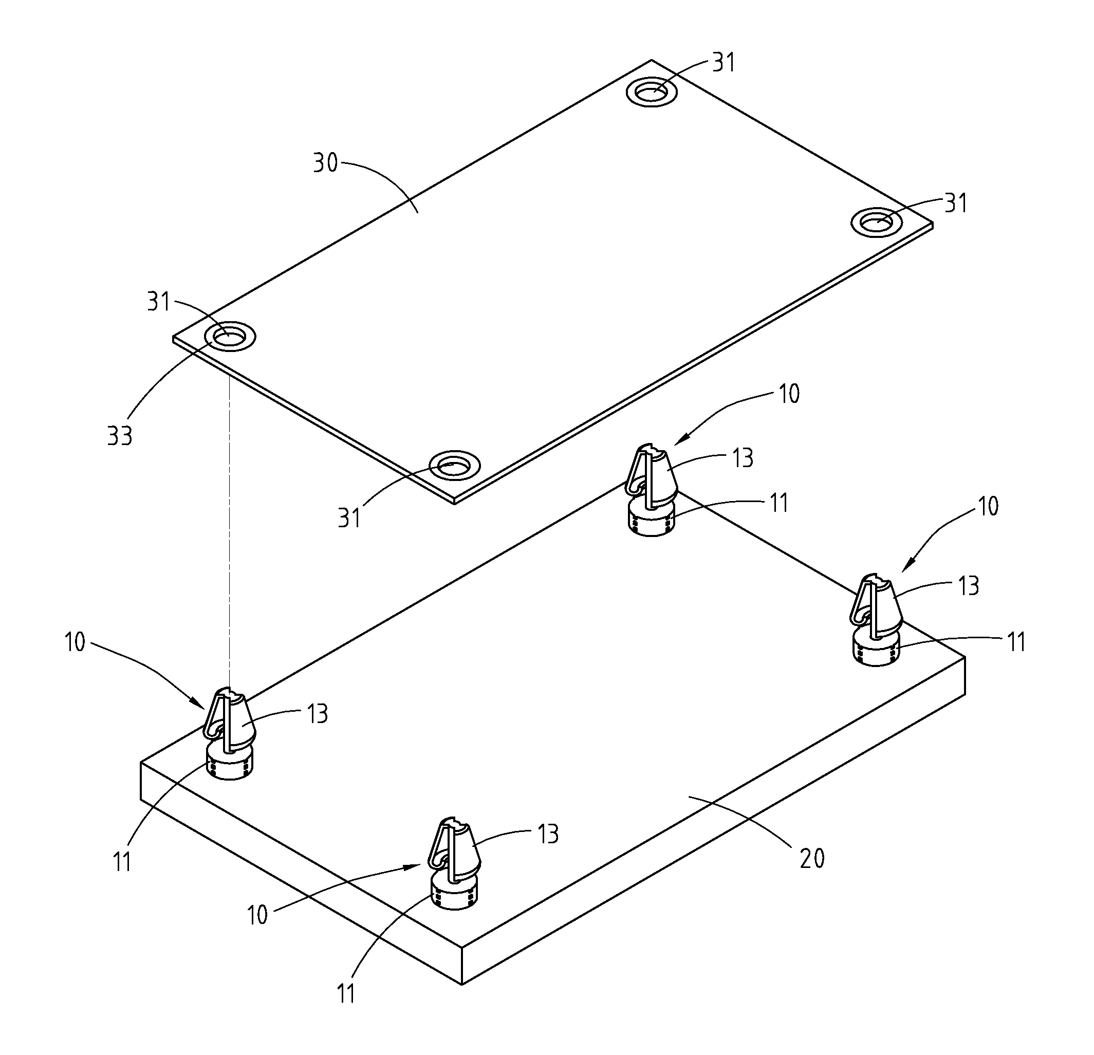
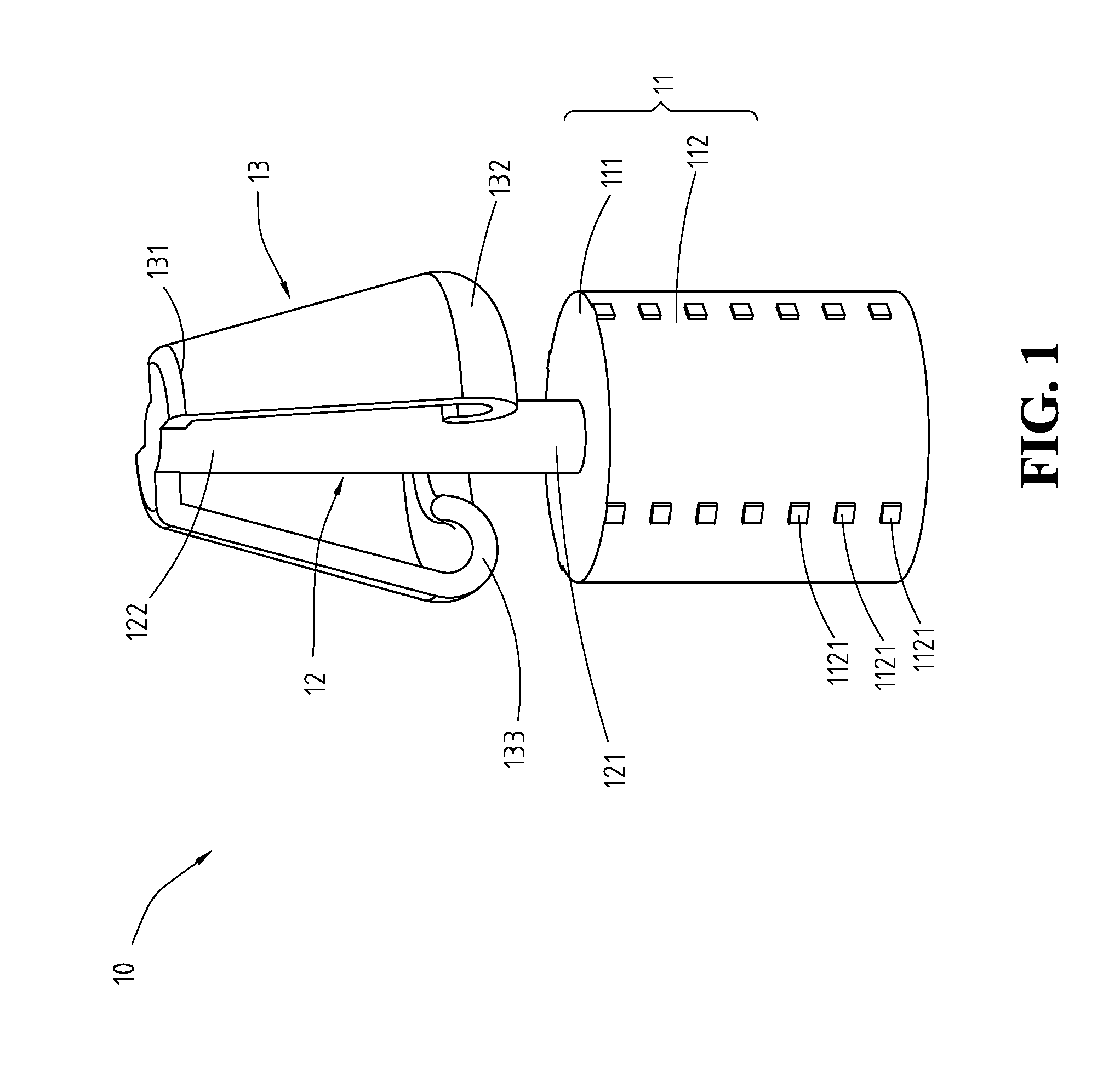
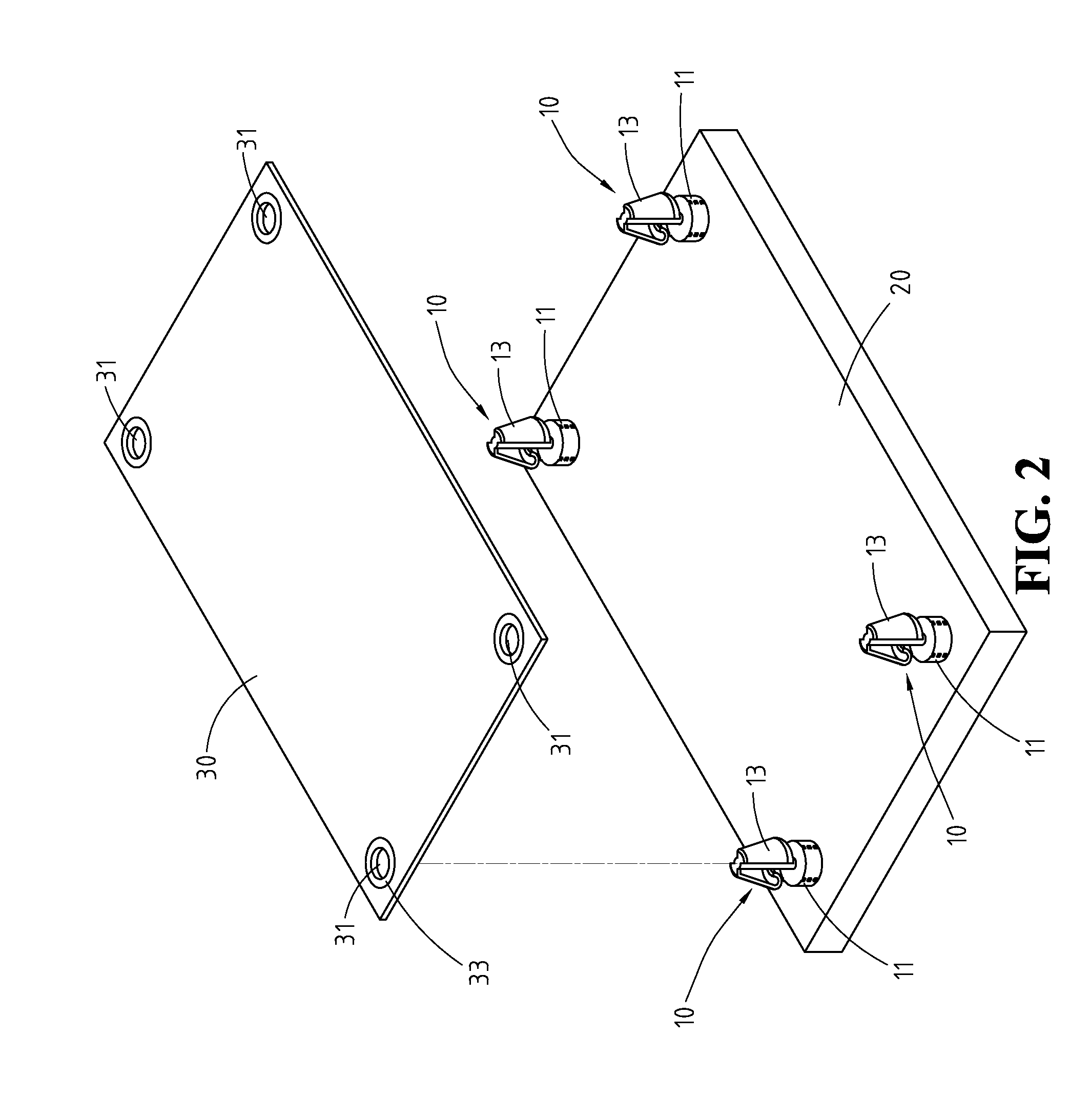
[0022]Please refer to FIG. 1 and FIG. 2, which are a perspective view of a flexible positioning post of a first embodiment and a schematic view for showing the flexible positioning post of the first embodiment is assembled on a housing. The flexible positioning post 10 includes a base 11, a metal post 12, and two metal elastic pieces 13. The base 11 has an upper surface 111 and a lateral surface 112. As shown in FIG. 1, the base 11 is round cylinder shaped in this embodiment, but embodiments of the disclosure are not limited thereto, in some implementation aspects, the base 11 is polygonal cylinder shaped. The upper surface 111 is the top face of the round cylindered base 11, and the lateral surface 112 is the surface of the body of the cylinder connected to the upper surface 111.

[0023]The lateral surface 112 has a plurality of protruding blocks 1121 disposed thereon. In this embodiment, the protruding blocks 1121 are disposed uniformly around the axis center of the lateral surface ...


PUM


Abstract

A flexible positioning post includes a base, a metal post and a plurality of metal elastic pieces. The base has an upper surface. The metal post has a first end and a second end opposite to each other, and the first end is connected to the upper surface of the base. Each of the metal elastic pieces has a fixed end and a free end opposite to each other. The fixed end is securely assembled at the second end of the metal post, and the free end is adjacent to the upper surface of the base and bent toward the metal post to form a bending portion. Consequently, upon receiving a foreign force, the free end of each of the metal elastic pieces is moved toward the metal post; conversely, once the foreign force is removed, the free end of each of the metal elastic pieces is moved resiliently.

Description

CROSS-REFERENCES TO RELATED APPLICATIONS[0001]This non-provisional application claims priority under 35 U.S.C. §119(a) on Patent Application No. 102221729 filed in Taiwan, R.O.C. on 2013 Nov. 20, the entire contents of which are hereby incorporated by reference.BACKGROUND[0002]1. Technical Field[0003]The disclosure relates to a flexible positioning post, and particularly to a flexible positioning post capable of being rapidly positioned and detached with a circuit board.[0004]2. Related Art[0005]The circuit boards must be positioned in the housing of the electronic devices. During the research and development procedures of the electronic devices, the circuit boards must also be positioned for testing. Conventionally, the circuit boards are fastened in the housing or the testing stage via the plastic locking members; for example, the plastic bolts are embedded into the housing, and the plastic nuts are applied to thread with the plastic bolts for positioning the circuit board; or the...

Claims


Application Information

Patent Timeline
Patent Type & Authority Applications(United States)
IPC IPC(8): F16B19/00
CPCF16B19/004F16B5/065F16B5/0664F16B21/086H05K7/142
Inventor LU, KUO-CHENGCHANG, WEN-CHENG
Owner WISTRON CORP
Learn More