
Two-motor multi-head 3D printer extrusion system

Inactive Publication Date: 2015-05-21
KONSTANTINOS JOSHUA FROST +1
View PDF19 Cites 65 Cited by
  • Summary
  • Abstract
  • Description
  • Claims
  • Application Information

AI Technical Summary

Benefits of technology

The patent describes a system that allows multiple printheads to work together without interfering with each other. This means that objects can be printed faster and larger by using a single printhead. This system also saves space and reduces costs.

Problems solved by technology

One of the problems with the traditional approach to 3D printers is the limitation of materials that can be simultaneously printed.
Generally, a reasonably priced 3D printer will only be able to print with a single material, because each different type of material requires its own printhead.
However, it is rare to see a FFF 3D printer with more than two print heads because of the difficulties and costs that arise and compound with each additional printhead.
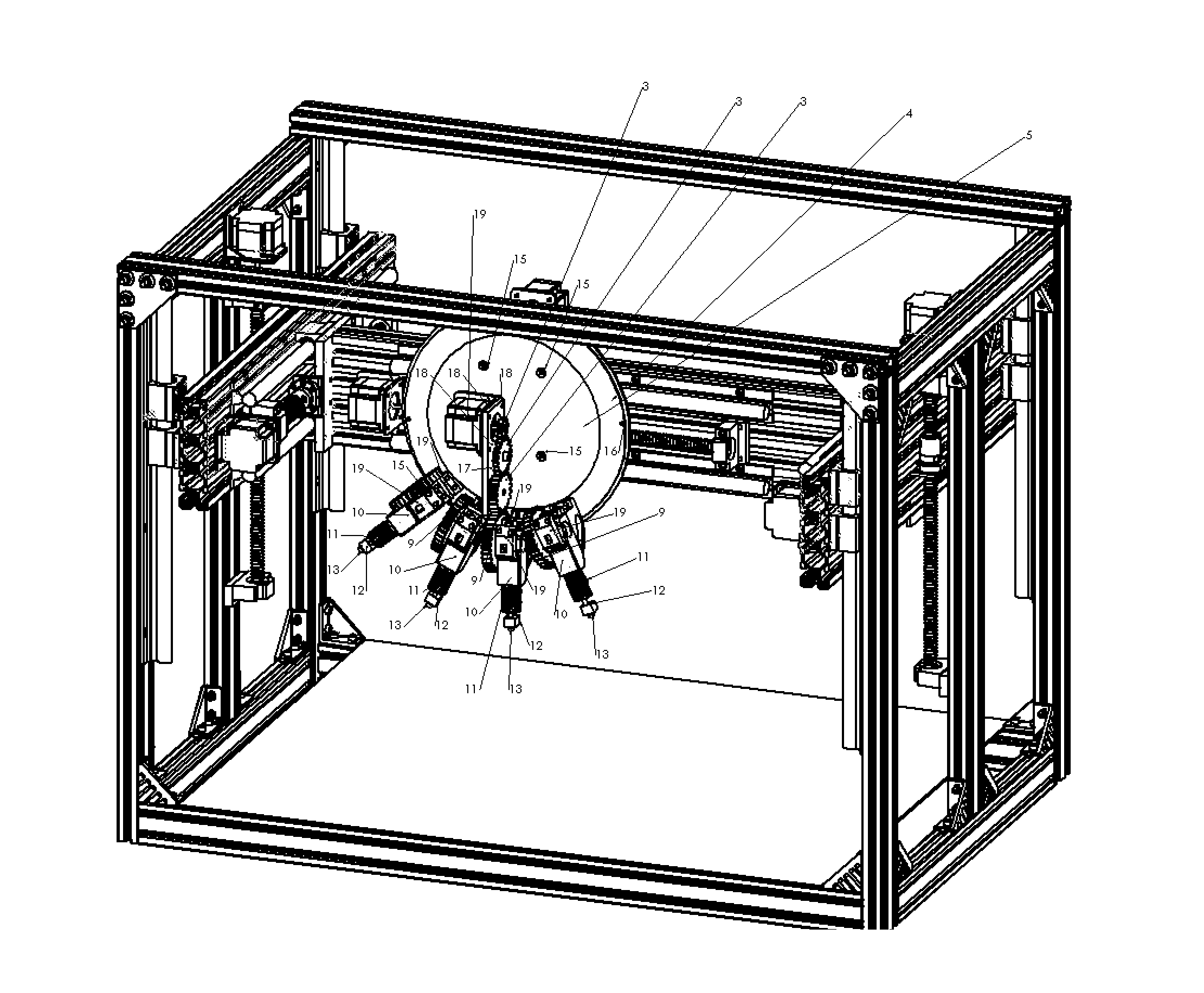
This orientation takes up valuable space on the x-axis thus reducing the ability of each of the heads to move along the full length of the x-axis in a gantry system, thus limiting the reach of each print head and ultimately the overall size of an object that can be created with a given 3D printer.
Another difficulty, in such style of printhead system having two or more printheads, is that the printhead currently in use must be at least slightly lower on the Z-axis than the other head(s), instead of being aligned.
Accordingly, these problems make it difficult and expensive to add more than two printheads to a typical 3D printing system.
While interesting, this patent does not resolve the issues with each printhead requiring a dedicated motor, and while it has described a method to keep multiple printheads from crashing into material extruded by the other heads it does so, by fixing the printheads and revolving the bed, in a manner that necessitates an extremely large number of printheads.
Moreover, this system would not work with existing software used to generate g-code from computer models or 3D scans.
They imagine that this design will allow for the use of multiple printheads without interference—although this would undoubtedly become more and more challenging as the number of printheads increased.
Again, a major limitation of this design is that in its attempt to add multiple printheads, it rejects the Cartesian gantry system, which means that you have lost compatibility with a large amount of existing tools and software designed for a Cartesian based system.
Moreover, this approach loses the benefit of compatibility with existing software for xyz gantry systems.
However, this translated application does not clarify issues with regard to the use of multiple printheads as used in an XYZ gantry system.
However, none of these patents solves the issue of space on the X-axis within a printing system or allows a number of printing heads to be driven by a single motor.

Method used


Image

  • Two-motor multi-head 3D printer extrusion system
  • Two-motor multi-head 3D printer extrusion system
  • Two-motor multi-head 3D printer extrusion system

Examples


Embodiment Construction

[0022]The embodiments of the invention and the various features and advantages thereto are more fully explained with references to the non-limiting embodiments and examples that are described and set forth in the following descriptions of those examples. Descriptions of well-known components and techniques may be omitted to avoid obscuring the invention. The examples used herein are intended merely to facilitate an understanding of ways in which the invention may be practiced and to further enable those skilled in the art to practice the invention. Accordingly, the examples and embodiments set forth herein should not be construed as limiting the scope of the invention, which is defined by the appended claims.

[0023]As used herein, terms such as “a,”“an,” and “the” include singular and plural referents unless the context clearly demands otherwise.

[0024]As used herein, the term “printing component” is a feature that can be used on the rotating ring to print material or otherwise modify...


PUM

PropertyMeasurementUnit
Shapeaaaaaaaaaa
Selectivityaaaaaaaaaa
Frictionaaaaaaaaaa

Abstract

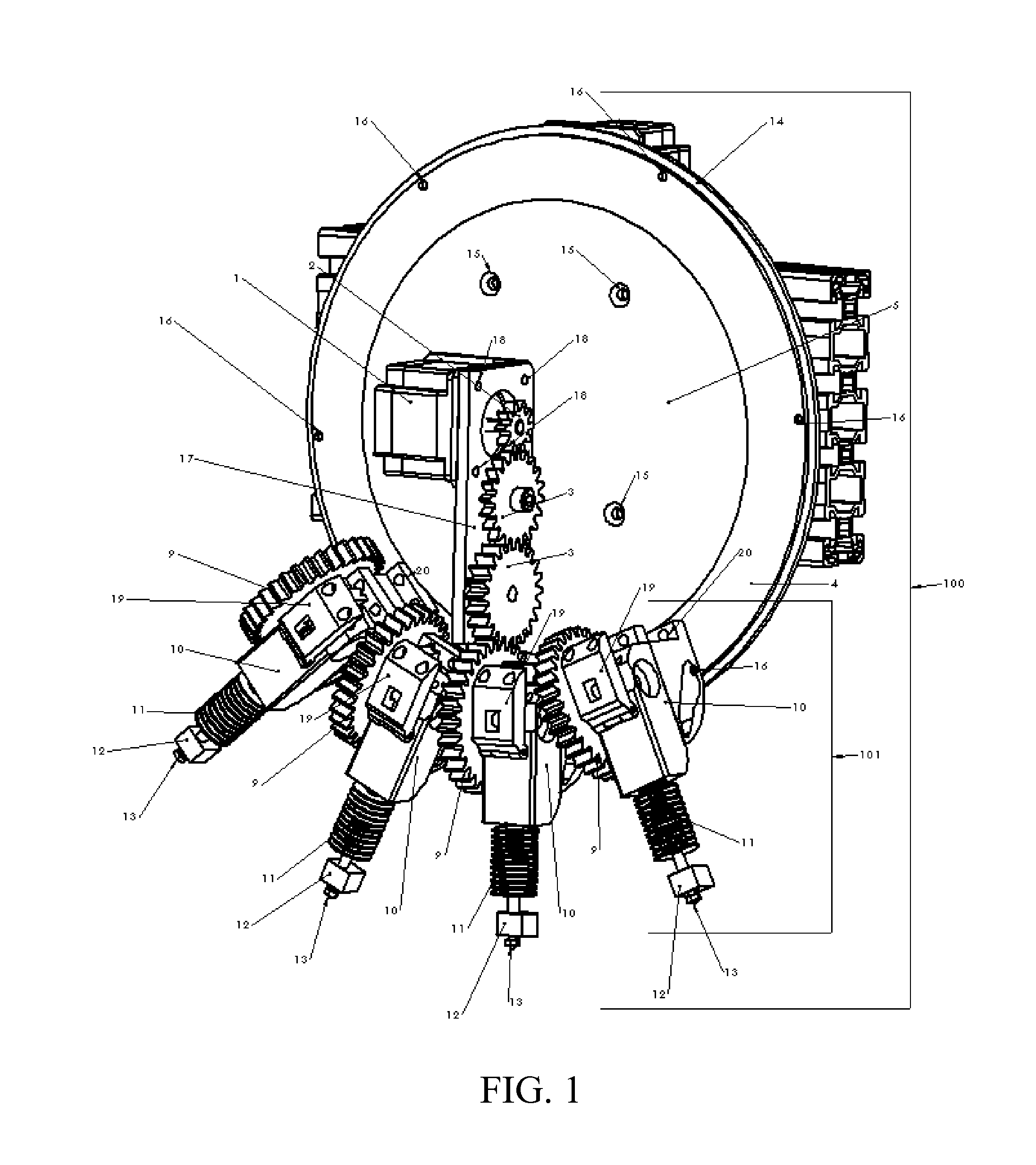
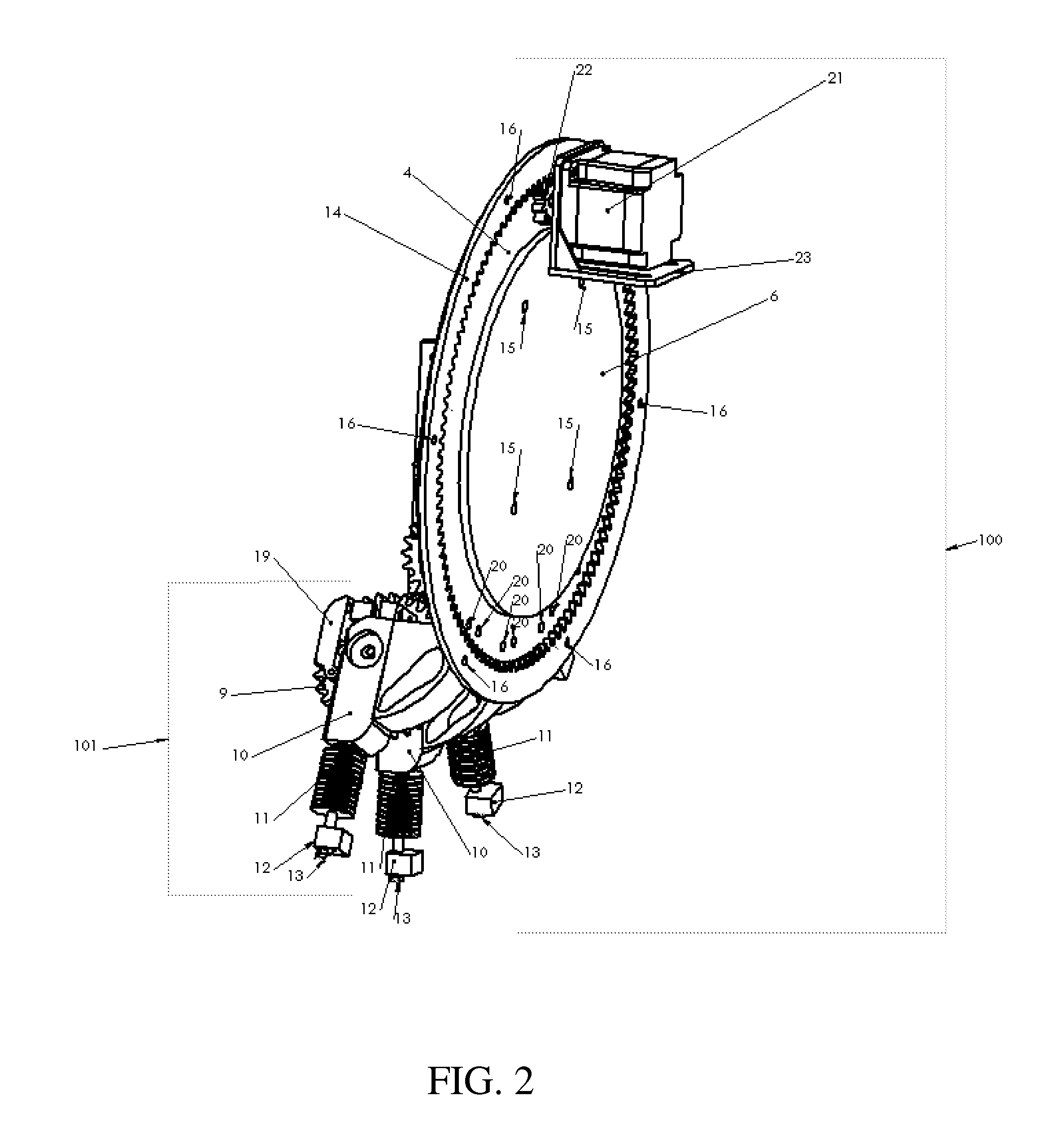
A 3D printing system having a rotating plate wherein at least two printing components are selectively attached to said rotating plate, and wherein said rotating plate is capable or rotating to selectively engage each said printing component to a drive motor which is capable of driving the printing component when engaged.

Description

[0001]This application claims priority to U.S. provisional application Ser. No. 61 / 904,868 filed Nov. 15, 2013, which is incorporated herein by reference in its entirety.FIELD OF INVENTION[0002]The present application is generally related to 3D printers, more specifically, to fused filament fabrication (FFF) type 3D printers. FFF type 3D printers apply layers of thermoplastics, usually ABS or PLA to create three-dimensional materials. Some FFF 3D printers may even be designed to use other metal or plastics composites suitable for FFF type 3D printing. This process was initially invented by S. Scott Crimp in 1989 as described in U.S. Pat No. 5,121,329.BACKGROUND OF THE INVENTION[0003]Typically, each printhead on a (FFF) 3D printer has its own dedicated motor, which will drive the plastic filament through the hot end of the device and out through the nozzle. The plastic filament thus is expelled out through the nozzle and applied to the printbed. Typically in a 3D printer, the positio...

Claims


Application Information

Patent Timeline
IPC IPC(8): B29C67/00
CPCB29C67/0051B29L2031/767B33Y30/00B29C64/118B29C64/241B29C64/106
Inventor KONSTANTINOS, JOSHUA FROSTSMOLUK, MICHAEL DONALD
Owner KONSTANTINOS JOSHUA FROST
Learn More