System and method for forming a curved tunnel in bone

Inactive Publication Date: 2015-05-21
SPECIALTY SURGICAL INSTR INC
View PDF3 Cites 8 Cited by
  • Summary
  • Abstract
  • Description
  • Claims
  • Application Information

AI Technical Summary

Benefits of technology

The invention describes a way to attach a ligament to a bone without using screws. This method has several advantages. Firstly, it reduces the risk of infection and rejection of the foreign object. Secondly, it simplifies the surgical procedure by making it a single curved path, as opposed to at least two separate paths from different directions. This reduces the complexity of the surgery and makes it faster. Lastly, there is no need for a separate device to pull the suture through the intersecting straight paths.

Problems solved by technology

These prior art procedures are invasive because they require drilling two separate intersecting openings from two different directions.
There is also the possibility that the two drilled openings do not intersect due to miscalculations of the drill path or inaccuracy in the drilling process.
This may result in drilling additional openings in the bone, which increases the level of complexity of the procedure, increases the operation time and also increases the bleeding risk of the patient.

Method used


Image

  • System and method for forming a curved tunnel in bone
  • System and method for forming a curved tunnel in bone
  • System and method for forming a curved tunnel in bone

Examples


Embodiment Construction

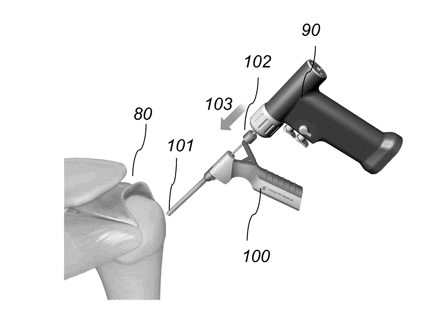
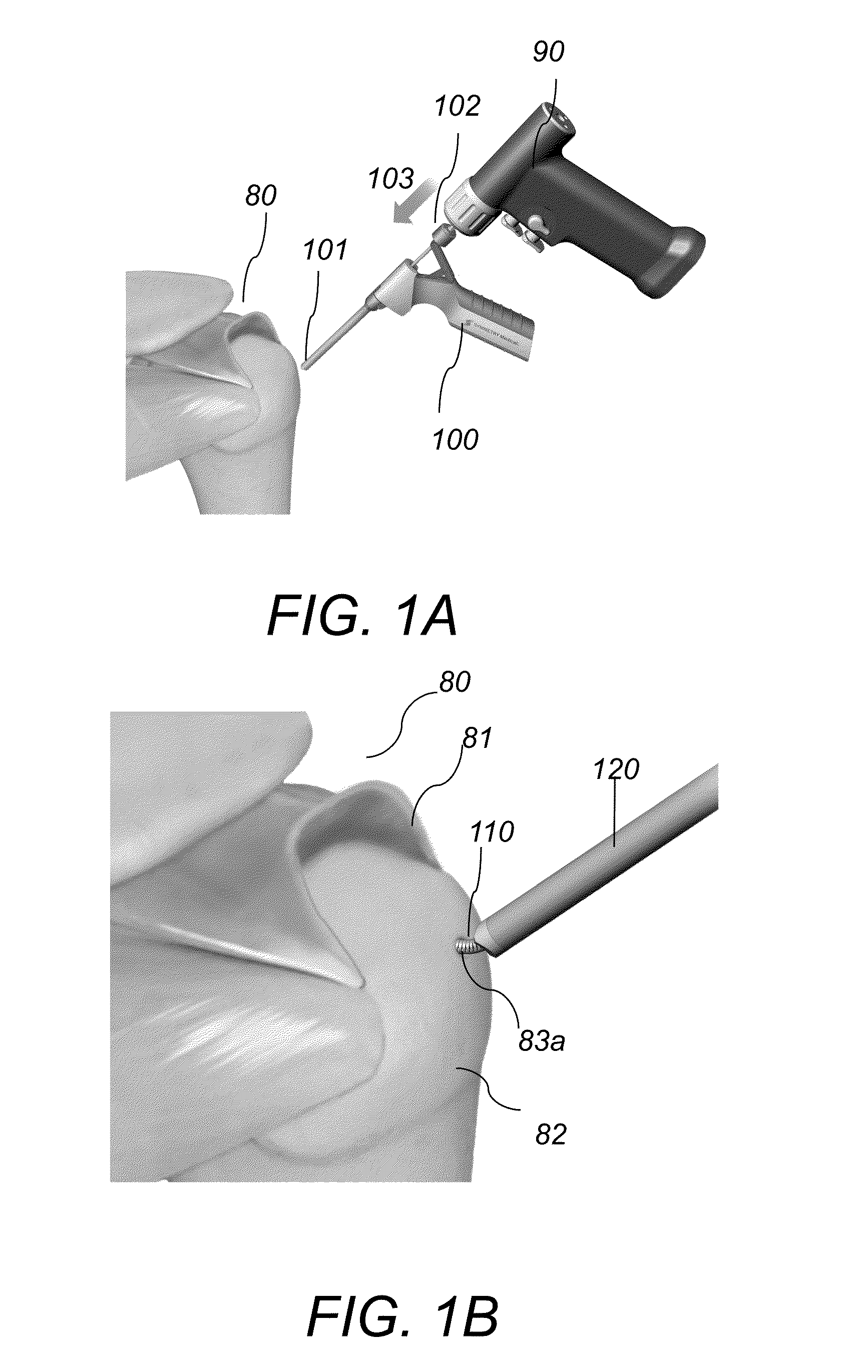
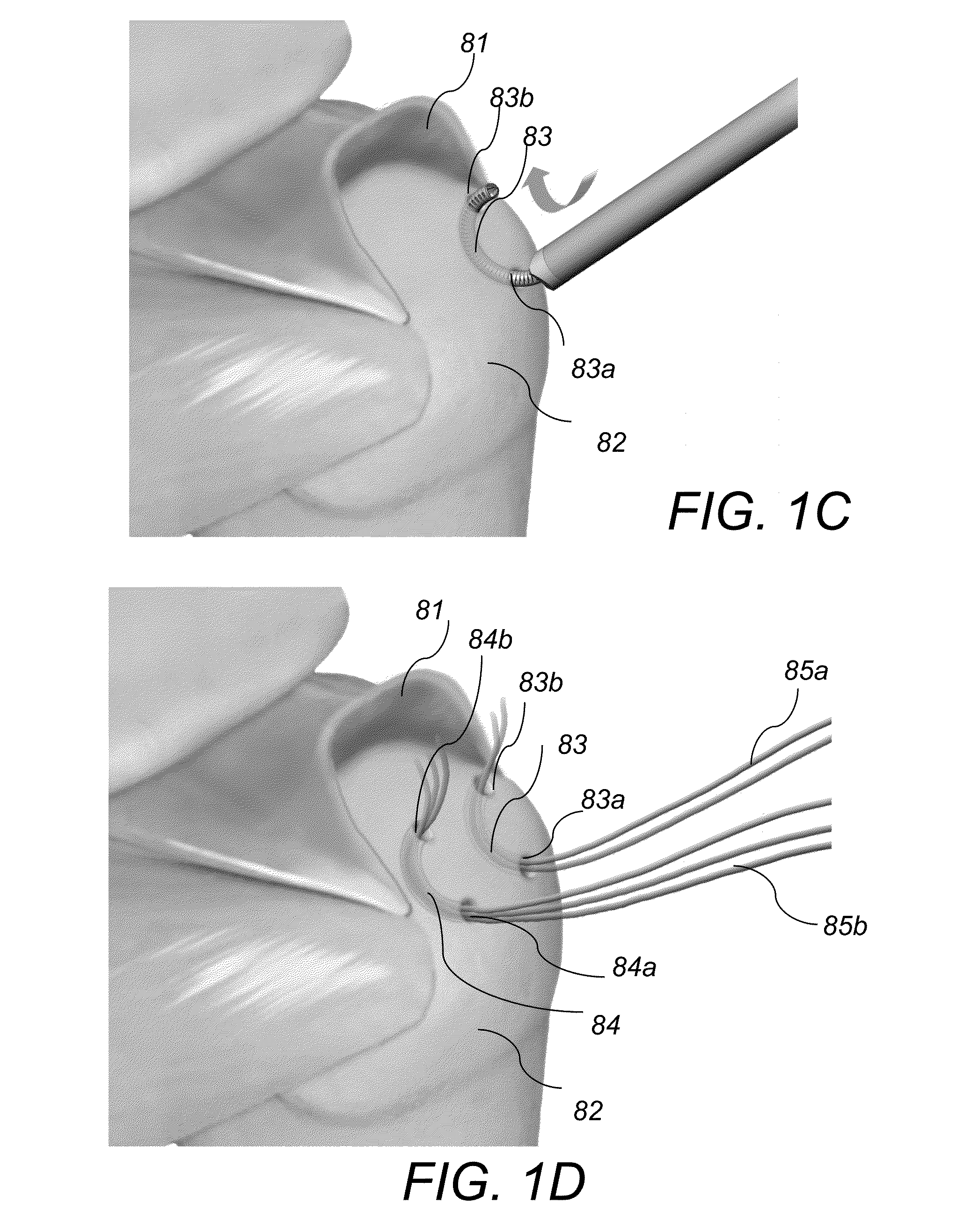
[0030]Referring to FIG. 1A-FIG. 1E, a ligament re-attachment surgical procedure in the rotator cuff area 80 includes the following. First, a drill 90 and a drill bit guidance device 100 are provided. Drill bit guidance device 100 is placed in front of drill 90 and includes a mechanism that guides the drill bit to drill a U-shaped curved tunnel. Next, the surgeon creates access to the bone area 82, and holds the distal end 101 of device 100 firmly against the bone 82 with one hand, while the other hand holds the power drill 90 that is attached to the proximal end 102 of the device 100. Next, the surgeon operates the drill 90 so that it rotates and he pushes the drill forward in the direction indicated by arrow 103 toward the distal end 101 of device 100, as shown in FIG. 1A. During this process, a drill bit or burr feeds through the distal end 101 of device 100 and enters a first bone location 83a. As the drill bit feeds out, it is guided by a tube 110 that causes the drill bit to mo...


PUM

PropertyMeasurementUnit
Angleaaaaaaaaaa
Lengthaaaaaaaaaa
Flexibilityaaaaaaaaaa

Abstract

A drill system for forming a curved tunnel in a bone includes a drill bit guidance device. The drill bit guidance device includes an elongated stationary outer tube extending along a first axis and an elongated inner tube assembly. The elongated inner tube assembly is configured to slidably move within the elongated stationary outer tube along the first axis and to exit from a distal end of the elongated outer tube. The elongated inner tube assembly includes an actuating tube and an actuator tube. The actuating tube slidably moves within the actuator tube and includes a plurality of semi-cross-sectional slots extending in a slot direction perpendicular to the first axis. Each slot of the actuating tube is configured to collapse inward in the slot direction when exiting the distal end of the elongated outer tube, thereby causing a distal end portion of the elongated inner tube assembly to follow a curved path.

Description

CROSS REFERENCE TO RELATED CO-PENDING APPLICATIONS[0001]This application is a continuation-in-part and claims the benefit of U.S. application Ser. No. 14 / 084,460 filed on Nov. 19, 2013 and entitled SYSTEM AND METHOD FOR FORMING A CURVED TUNNEL IN BONE, which is commonly assigned and the contents of which are expressly incorporated herein by reference.FIELD OF THE INVENTION[0002]The present invention relates to a system and a method for forming a curved tunnel in a bone and in particular to device that uses a tube with a slotted front end to form a U-shaped tunnel in the bone.BACKGROUND OF THE INVENTION[0003]In several surgical procedures opening of curved tunnels in bone is needed. Examples of these type of surgical procedures include rotator cuff repair and Achilles tendon repair where re-attaching of muscle and ligaments to bone is performed.[0004]Prior art technologies for performing these type of surgical procedures involve drilling two separate openings that have intersecting s...

Claims


Application Information

Patent Timeline
IPC IPC(8): A61B17/16
CPCA61B17/1642A61B17/04A61B17/1624A61B17/1631A61B17/1633A61B17/1796A61B2017/00309A61B2017/00323Y10T29/49826
Inventor KIAPOUR, ALIFERNANDEZ, JOSE
Owner SPECIALTY SURGICAL INSTR INC
Why Eureka
Try Eureka