Electrode for Implantation in a Living Organ and a Method for Implanting the Elecrode

Inactive Publication Date: 2009-11-05
MEDTRONIC INC
View PDF3 Cites 0 Cited by
  • Summary
  • Abstract
  • Description
  • Claims
  • Application Information

AI Technical Summary

Benefits of technology

[0019]The relatively rigid introduction part, arranged to engage with said abutment area of the electrode head, makes it possible to introduce the electrode head in an easy, convenient and controllable way into the submucosa, even though a very thin and/or flexible cable. Such a flexible cable is very advantageous, since it allows the electrod

Problems solved by technology

The states of ill-health that result in disorder of the motor functions of the stomach and the intestinal canal still are not fully understood, although they may seriously handicap afflicted patient groups.
This condition may be very difficult to treat.
Both implantation methods are serious operations requiring that the patient be anaesthetized.
Implantation of electrodes into a stomach wall poses special problems since the organ wall yields as the electrodes are being implanted.
In addition, the risks of inadvertent puncture of the stomach wall are not negligible.
Not only would such an implantation method reduce the costs with respect to the operation as such and to the hospitalization of the patient, but it would also decrease patient discomfort.
Further, it has been empirically established that some patients do not react positively on the pacemaker treatment, and on such patient these relatively complicated, cumbersome and expensive operations are

Method used


Image

  • Electrode for Implantation in a Living Organ and a Method for Implanting the Elecrode
  • Electrode for Implantation in a Living Organ and a Method for Implanting the Elecrode
  • Electrode for Implantation in a Living Organ and a Method for Implanting the Elecrode

Examples


Embodiment Construction

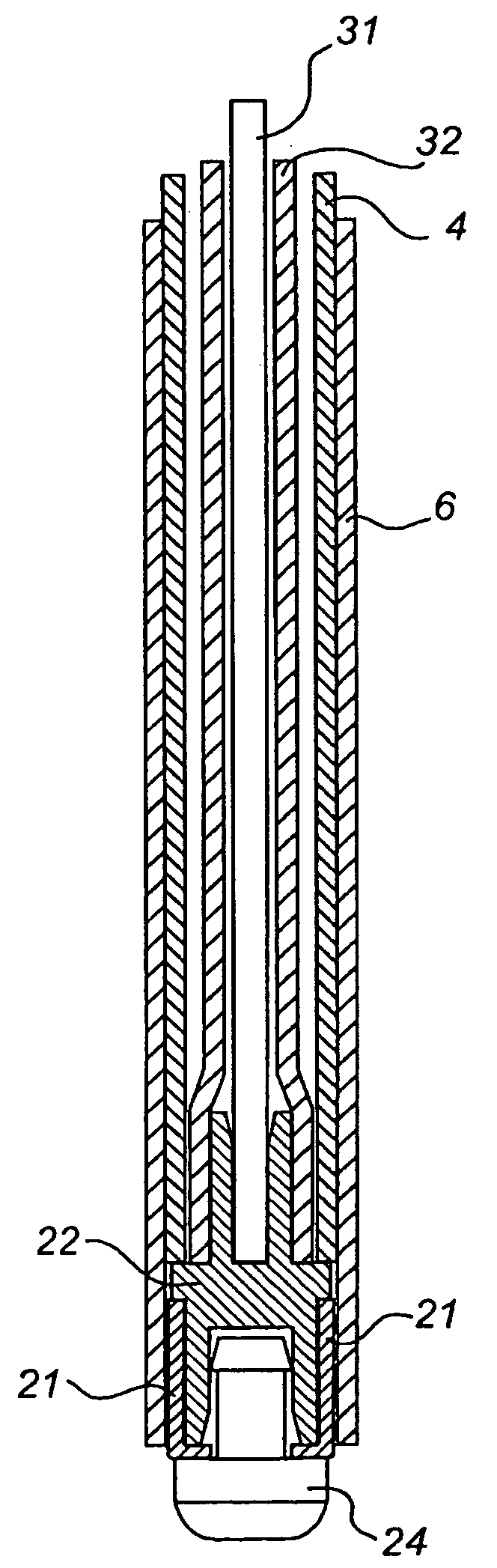
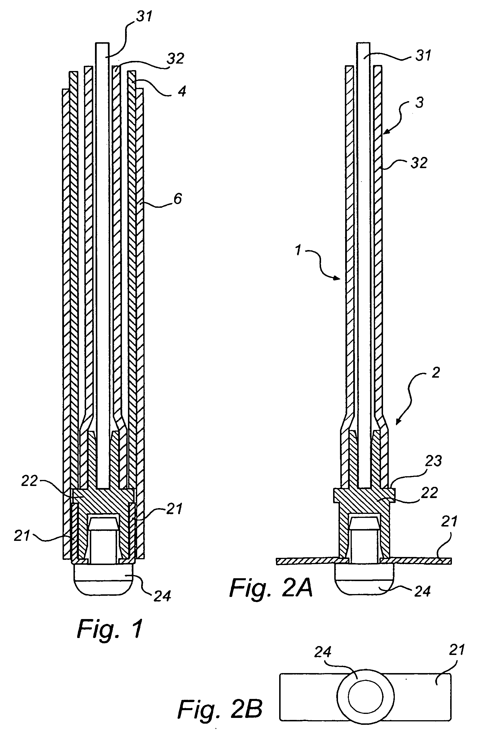
[0034]In a first embodiment of the gastrointestinal electrode device according to the invention, is illustrated in FIG. 1-3. The gastrointestinal electrode device 1 comprises an electrode head 2 intended to be implanted in a stomach wall for emission or reception of electrical signals and a flexible cable 3 with an inner conductor 31 and an outer isolation layer 32. The flexible cable is connected to the electrode head for forwarding the electric signals to electronic equipment (not shown) on the external side, such as a pacemaker or measurement unit. The flexible cable is very thin and / or flexible, so as to be easily bent and folded.

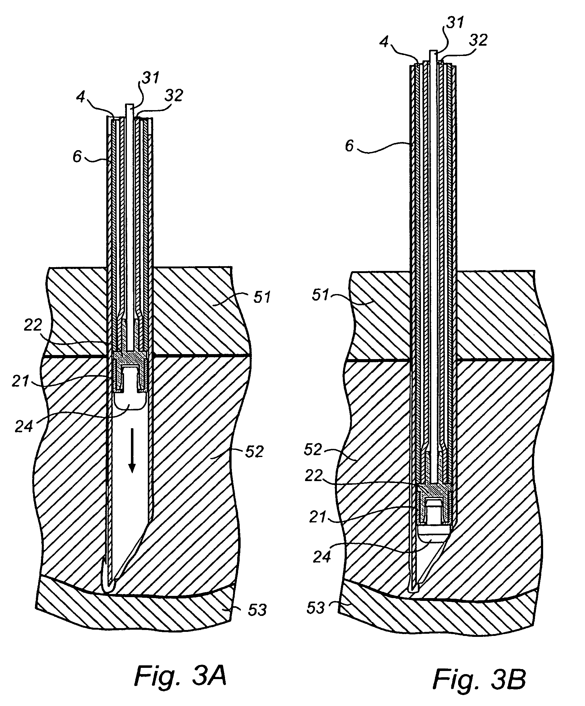
[0035]The electrode head 2 comprises flexible expandable retention wings 21, arranged to automatically expand from an condition of insertion, as illustrated in FIG. 1, into an expanded condition for opposing retraction of the electrode via the aperture of insertion, as illustrated in FIG. 2, thus making the electrode attachable to the living organ. The ...


PUM


Abstract

A gastrointestinal electrode device is disclosed, comprising an electrode head intended to be implanted in a stomach wall for emission or reception of electrical signals and a flexible cable with an outer isolation layer. The flexible cable is connected to the electrode head for forwarding the electric signals to an external side of the electrode device. The electrode head comprises flexible expandable retention means and at least one electrode contact area arranged to cover at least a part of the outer electrode head area. Further the expandable retention means are automatically expandable from an condition of insertion into an expanded condition for opposing retraction of the electrode via the aperture of insertion, thus making the electrode attachable to the living organ. The electrode head further comprises an abutment area and the electrode device further comprises a relatively rigid introduction part, arranged to engage with the abutment area of the electrode head for percutaneous introduction of the catheter into a stomach wall into a stomach wall via an aperture, wherein the introduction part is releasable from the electrode head after insertion, whereby the electrode head remains implanted in the stomach wall.

Description

FIELD OF THE INVENTION[0001]The present invention relates to an electrode intended to be implanted into a living organ, such as the stomach, for emission or reception of electrical signals, and to be connected to an electric device, such as e. g. a pacemaker.BACKGROUND OF THE INVENTION[0002]The states of ill-health that result in disorder of the motor functions of the stomach and the intestinal canal still are not fully understood, although they may seriously handicap afflicted patient groups. A condition known as gastropares (i. e. cease of motor function in the stomach) may afflict for instance patients suffering from highly advanced diabetes. This condition may be very difficult to treat. In order to decrease symptoms and improve motor functions of the intestinal canal under these circumstances and thus to accelerate the bowel movements, the pacemaker technique can be used.[0003]The pacemaker technique is well-known for mechanical-electrical control of the nerves of a living orga...

Claims


Application Information

Patent Timeline
IPC IPC(8): A61N1/05
CPCA61N1/36007A61N1/0509
Inventor ABRAHAMSSON, HASSELONROTH, HANS
Owner MEDTRONIC INC
Why Eureka
Try Eureka