Compression-release engine brake system for lost motion rocker arm assembly and method of operation thereof

a technology of compression release and engine, which is applied in the direction of valve arrangements, machines/engines, non-mechanical valves, etc., can solve the problems of engine overhead damage, reduced braking performance, and reduced exhaust stroke work, so as to achieve optimum retarding power, reduce cost, and operate quietly

Active Publication Date: 2015-05-28
PACBRAKE
View PDF2 Cites 57 Cited by
  • Summary
  • Abstract
  • Description
  • Claims
  • Application Information

AI Technical Summary

Benefits of technology

[0014]The compression-release brake system of the present invention is low cost and can be integrated into the overall engine design. Moreover, the present invention provides a compression-release brake system that is lightweight, does not mechanically and thermally overload the engine system, has quiet operation and yields optimum retarding power over the entire engine speed range where the engine brake is used.

Problems solved by technology

One problem with the conventional rocker arm brake system is that valve overlap at exhaust / intake is extended and thus braking performance decreased.
Moreover, a problem with opening a single valve is that exhaust / intake overlap is extended and the opening up an exhaust bridge is unbalanced during the initial normal exhaust lift and might result in engine overhead damage.
In other words, the extended valve overlap causes an undesired exhaust manifold air mass flow into the engine intake system, thus reducing exhaust stroke work and decreasing braking performance.
These limitations include valve train loading, engine design limits, emissions regulations and other considerations.

Method used


Image

  • Compression-release engine brake system for lost motion rocker arm assembly and method of operation thereof
  • Compression-release engine brake system for lost motion rocker arm assembly and method of operation thereof
  • Compression-release engine brake system for lost motion rocker arm assembly and method of operation thereof

Examples


Embodiment Construction

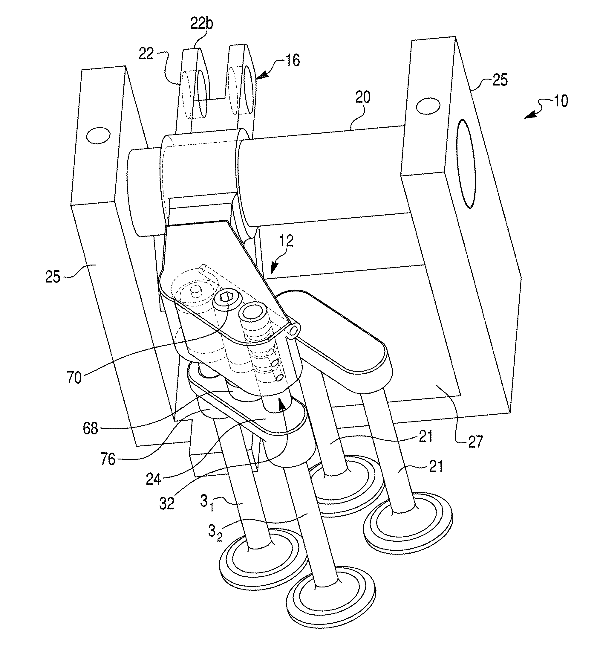
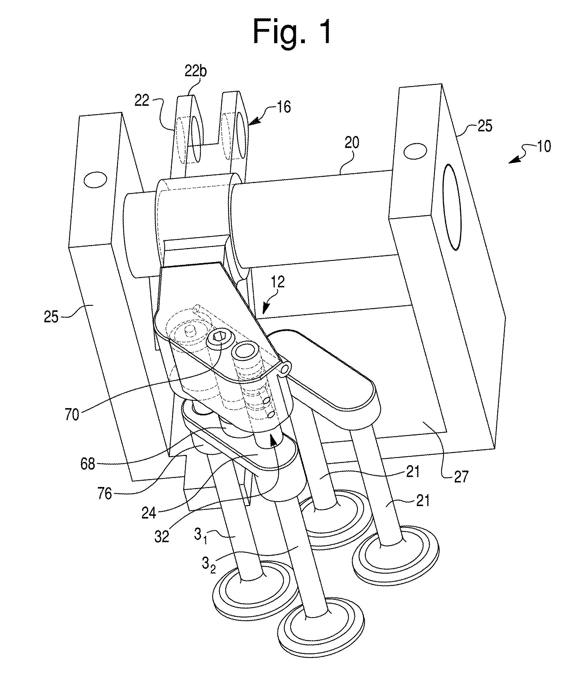
[0047]Reference will now be made in detail to exemplary embodiments and methods of the invention as illustrated in the accompanying drawings, in which like reference characters designate like or corresponding parts throughout the drawings. It should be noted, however, that the invention in its broader aspects is not limited to the specific details, representative devices and methods, and illustrative examples shown and described in connection with the exemplary embodiments and methods.

[0048]This description of exemplary embodiments is intended to be read in connection with the accompanying drawings, which are to be considered part of the entire written description. In the description, relative terms such as “horizontal,”“vertical,”“front,”“rear,”“upper”, “lower”, “top” and “bottom” as well as derivatives thereof (e.g., “horizontally,”“downwardly,”“upwardly,” etc.) should be construed to refer to the orientation as then described or as shown in the drawing figure under discussion and...


PUM


Abstract

A compression-release brake system comprises an exhaust rocker arm, an actuation piston slidable in a piston bore in the exhaust rocker arm so as to press an exhaust valve, a supply conduit formed within the exhaust rocker arm, and an exhaust valve reset device mounted to the exhaust rocker arm. The actuation piston defines an actuation piston cavity within the actuation piston bore between the piston bore and the actuation piston. The exhaust valve reset device includes a reset check valve disposed between the supply conduit and the actuation piston cavity to hydraulically lock the actuation piston cavity by closing the reset check valve when a pressure of the hydraulic fluid within the actuation piston cavity exceeds the pressure of the hydraulic fluid in the supply conduit. The reset check valve is biased closed by the pressure of the hydraulic fluid within the actuation piston cavity during the brake-on mode.

Description

CROSS-REFERENCE TO RELATED APPLICATIONS[0001]This application claims the benefit of provisional applications No. 61 / 908,272 filed on Nov. 25, 2013 by V. Meneely and R. Price, and of No. 62 / 001,392 filed on May 21, 2014 by V. Meneely and R. Price, which are hereby incorporated herein by reference in their entirety and to which priority is claimed.BACKGROUND OF THE INVENTION[0002]1. Field of the Invention[0003]The present invention relates to compression-release engine brake systems in general, and more particularly to a compression-release engine brake system and method comprising a lost motion type engine brake rocker arm assembly incorporating structure implementing a valve reset function.[0004]2. Description of the Related Art[0005]Compression release engine brake systems (or retarders) for diesel engines were designed and developed in North America starting in the early 1960's. There have been many changes that have been implemented that have increased retarding performance, redu...

Claims


Application Information

Patent Timeline
Patent Type & Authority Applications(United States)
IPC IPC(8): F01L13/06F02D13/04F01L9/10
CPCF02D13/04F01L13/06F01L1/18F01L1/181F01L1/26F01L13/065F01L9/10F01L1/462
Inventor MENEELY, VINCENTPRICE, ROBERT
Owner PACBRAKE
Why Eureka
Try Eureka