Operation device

a technology of operation device and contact, which is applied in the direction of gearing control, contact fixed to the operating part, gearing element, etc., can solve the problem of difficult to determine whether both the contact is in an on state or an off state, and achieve the effect of improving the accuracy of failure detection and more reliable gear shifting

Active Publication Date: 2015-05-28
ALPS ALPINE CO LTD
View PDF5 Cites 10 Cited by
  • Summary
  • Abstract
  • Description
  • Claims
  • Application Information

AI Technical Summary

Benefits of technology

[0012]The present invention provides an operation device capable of generating an operation signal by switch input and determining a failure more reliably when the contact of one location fails.
[0014]According to this configuration, at the time of ON operation by the switch input, the reference contact circuit is turned on at a timing earlier than the other output contact circuits. In this case, it is possible to output a signal indicating the state of ON operation when the reference contact circuit is in a state of ON operation and the other output contact circuits are in an ON state. When the reference contact circuit is in an OFF state and any one of the other output contact circuits is in an ON state, it is possible to determine that either the reference contact circuit or any one of the output contact circuits in an ON state has certainly failed and to display an alarm or the like. Therefore, since it is possible to improve the accuracy of failure detection when the contact of one location fails, it is possible to increase safety by determining a failure more reliably.
[0022]According to this configuration, since a sliding contact mechanism is used in which the switching of contacts is performed by sliding contact between the fixed terminals and the slider, it is possible to increase the safety of the operation device.
[0024]According to this configuration, it becomes easy to manufacture the operation device by using a switch unit, which includes the movable contact and the fixed electrodes, for the plurality of contact circuits.
[0026]By using the operation device for the operation of the vehicle transmission, it is possible to perform more reliable gear shifting.
[0027]According to the aspect of the present invention, the reference contact circuit is provided such that the distance from the initial position where the movable contact starts to move to the position where the reference contact circuit is turned on is smaller than that for the output contact circuits. In this case, it is possible to output a signal indicating the state of ON operation when the reference contact circuit is in a state of ON operation and the other output contact circuits are in an ON state. When the reference contact circuit is in an OFF state and any one of the other contact circuits is in an ON state, it is possible to determine that either the reference contact circuit or any one of the contact circuits in an ON state has certainly failed and to display an alarm or the like. Therefore, since it is possible to generate an operation signal by switch input and to improve the accuracy of failure detection when the contact of one location fails, it is possible to provide an operation device capable of determining a failure more reliably.

Problems solved by technology

Therefore, in the control device 200 in the related art, it has been difficult to determine whether both the contacts are in an ON state or in an OFF state due to the transient period or the half-pressed state or both the contacts are in an ON state or in an OFF state due to the fixation of any one of the contacts.
This problem is the same for a switch structure including two normally open contacts.

Method used


Image

  • Operation device
  • Operation device
  • Operation device

Examples


first embodiment

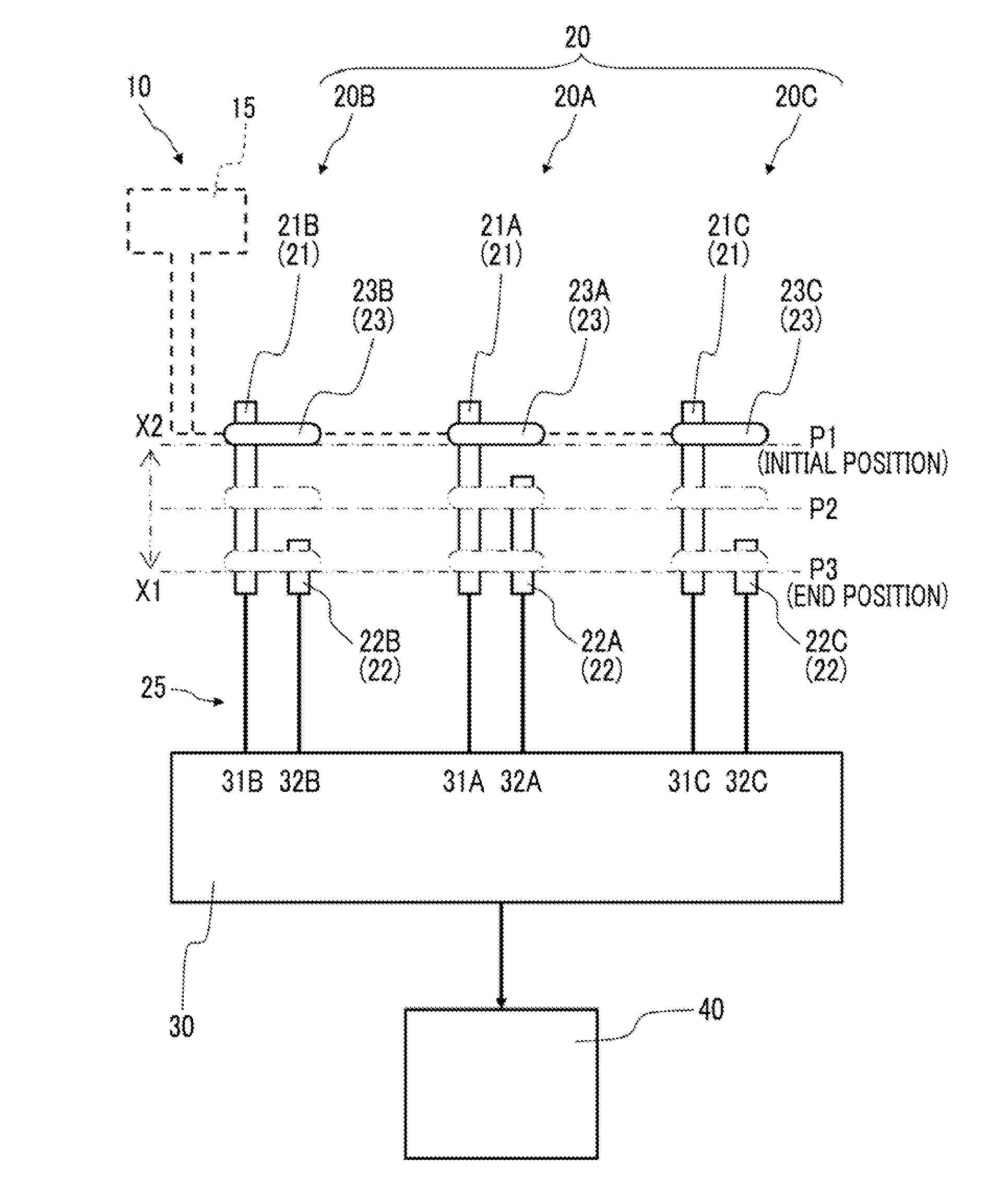
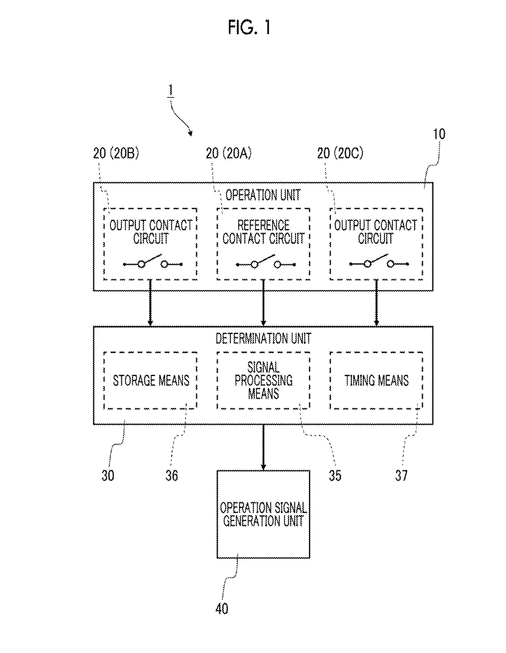
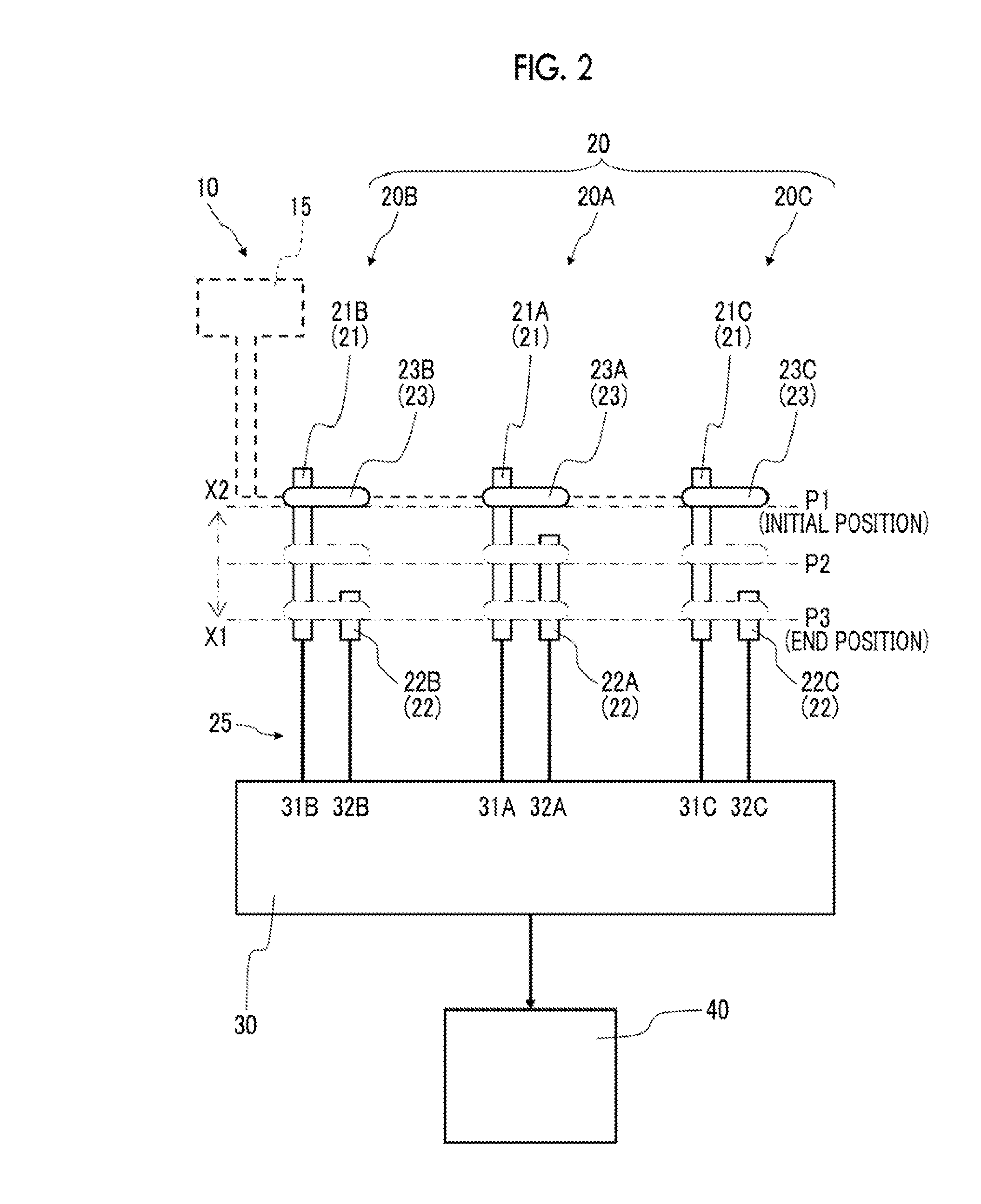
[0055]FIG. 1 is a block diagram showing an operation device 1 according to a first embodiment of the present invention. FIG. 2 is an explanatory view showing an operation unit 10 shown in FIG. 1. FIG. 3 is an explanatory view when the operation device 1 according to the first embodiment of the present invention is applied to a vehicle transmission 61. FIG. 4 is an explanatory view showing a state in which a slider 23 of the operation unit 10 shown in FIG. 2 is located at an initial position P1. FIG. 5 is an explanatory view showing a state in which the slider 23 of the operation unit 10 shown in FIG. 2 is located at a position P2 of a transient state. FIG. 6 is an explanatory view showing a state in which the slider 23 of the operation unit 10 shown in FIG. 2 is located at an end position P3.

[0056]As shown in FIG. 1, the operation device 1 according to the present embodiment includes the operation unit 10, a determination unit 30, and an operation signal generation unit 40. The oper...

second embodiment

[0101]FIG. 16 is a block diagram showing an operation device 2 according to a second embodiment of the present invention. FIG. 17 is an explanatory view showing an operation unit 70 shown in FIG. 16. FIG. 18 is an explanatory view showing a contact circuit 80 in cross-sectional view. FIGS. 19A and 19B are explanatory views showing fixed electrodes 81Aa and 82Aa, where FIG. 19A shows fixed electrodes in plan view and FIG. 19B is a cross-sectional view taken along the line B-B of FIG. 19A. FIG. 20 is an explanatory view when the operation device 2 according to the second embodiment is applied to a vehicle transmission 61. FIG. 21 is an explanatory view showing a state in which the contact circuit 80 shown in FIG. 18 is located at an initial position P4. FIG. 22 is an explanatory view showing a state in which the contact circuit 80 shown in FIG. 18 is located at a position P5 of a transient state. FIG. 23 is an explanatory view showing a state in which the contact circuit 80 shown in F...


PUM


Abstract

An operation device includes three contact circuits each including fixed terminals and a slider as a movable contact for selectively changing a state between the fixed terminals to an ON / OFF state, a determination unit to which the contact circuits are connected, and an operation signal generation unit that outputs a signal indicating that an operation unit is in a state of ON operation. In response to an ON operation, the slider moves from an initial position where all contact circuits are in an OFF state to an end position where all contact circuits are turned on. Assuming that one of the contact circuits is a reference contact circuit and the others are output contact circuits, the reference contact circuit is provided such that a distance from the initial position to a position where the reference contact circuit is turned on is smaller than that for the output contact circuits.

Description

CLAIM OF PRIORITY[0001]This application claims benefit of Japanese Patent Application No. 2013-244741 filed on Nov. 27, 2013, which is hereby incorporated by reference.BACKGROUND OF THE INVENTION[0002]1. Field of the Invention[0003]The present invention relates to an operation device that generates an operation signal by a switch input, and in particular, to an operation device that can increase safety by determining a failure more reliably.[0004]2. Description of the Related Art[0005]A switch input for ON / OFF of the contact of an electrical circuit is used in an operation device for controlling various apparatuses. For example, a switch input is used in an operation device for vehicles that is used to operate a vehicle transmission for driving control of the vehicle with an electrical operation signal.[0006]Japanese Patent No. 3912344 discloses a control device 200 of an automatic transmission with a manual mode that allows manual mode switching or manual shift operation. FIG. 26 i...

Claims


Application Information

Patent Timeline
Patent Type & Authority Applications(United States)
IPC IPC(8): H01H15/10
CPCH01H2205/002H01H15/10F16H59/02F16H59/105F16H61/12H01H2300/02
Inventor NIKAMI, FUMIHITOINOMATA, SATORUKAWANO, KENJIONODERA, KAZUNOBU
Owner ALPS ALPINE CO LTD
Why Eureka
Try Eureka