Aircraft fuselage portion in composite material including ply drop-off with gentle slope

Inactive Publication Date: 2015-05-28
AIRBUS OPERATIONS SAS
View PDF7 Cites 5 Cited by
  • Summary
  • Abstract
  • Description
  • Claims
  • Application Information

AI Technical Summary

Benefits of technology

[0018]An aim of the invention is notably to provide a simple, economical and effective solution to this problem that makes it possible to make th

Problems solved by technology

One difficulty encountered in the production of aircraft fuselages lies in the operation of assembling the circumferential frames with the fuselage skin in the case where the circumferential frames each have a soleplate in contact with the fuselage skin.
The operation is tedious and costly in time, in particular

Method used


Image

  • Aircraft fuselage portion in composite material including ply drop-off with gentle slope
  • Aircraft fuselage portion in composite material including ply drop-off with gentle slope
  • Aircraft fuselage portion in composite material including ply drop-off with gentle slope

Examples


Embodiment Construction

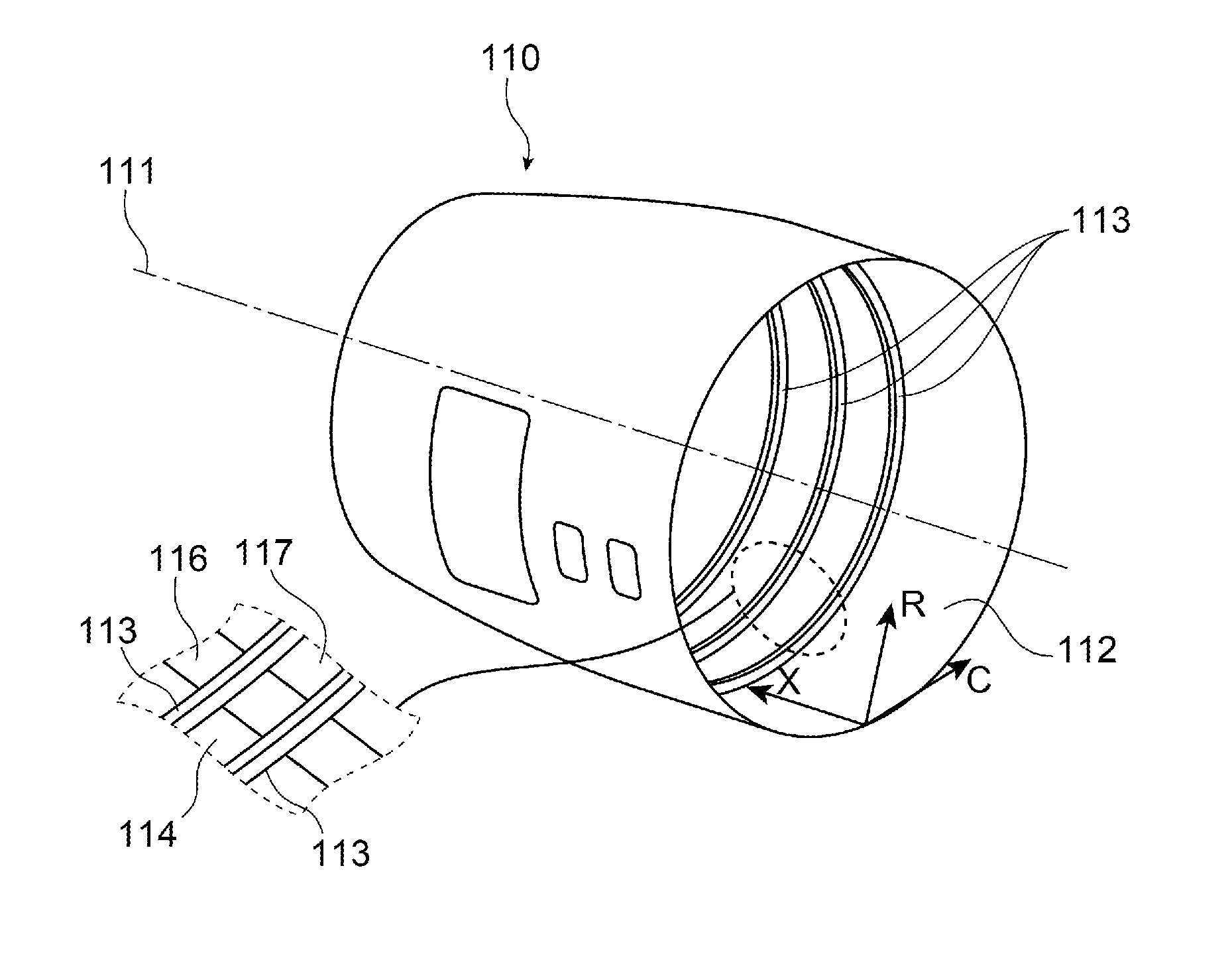
[0040]FIG. 5 illustrates a fuselage portion 110 intended to form a forward section of an aircraft fuselage. This fuselage portion 110 extends along an axis 111 defining a longitudinal direction X of the fuselage portion. Radial R and circumferential C directions are also defined by reference to the axis 111.

[0041]This fuselage portion 110 comprises a fuselage skin 112 in composite material and circumferential frames 113 intended to rigidify the fuselage skin 112, in a manner known per se.

[0042]In the example illustrated, the fuselage portion 110 has no stringers, that is to say longitudinal stiffeners. The rigidity of the fuselage skin 112 is thus obtained through the thickness of this skin, in a manner known to those skilled in the art.

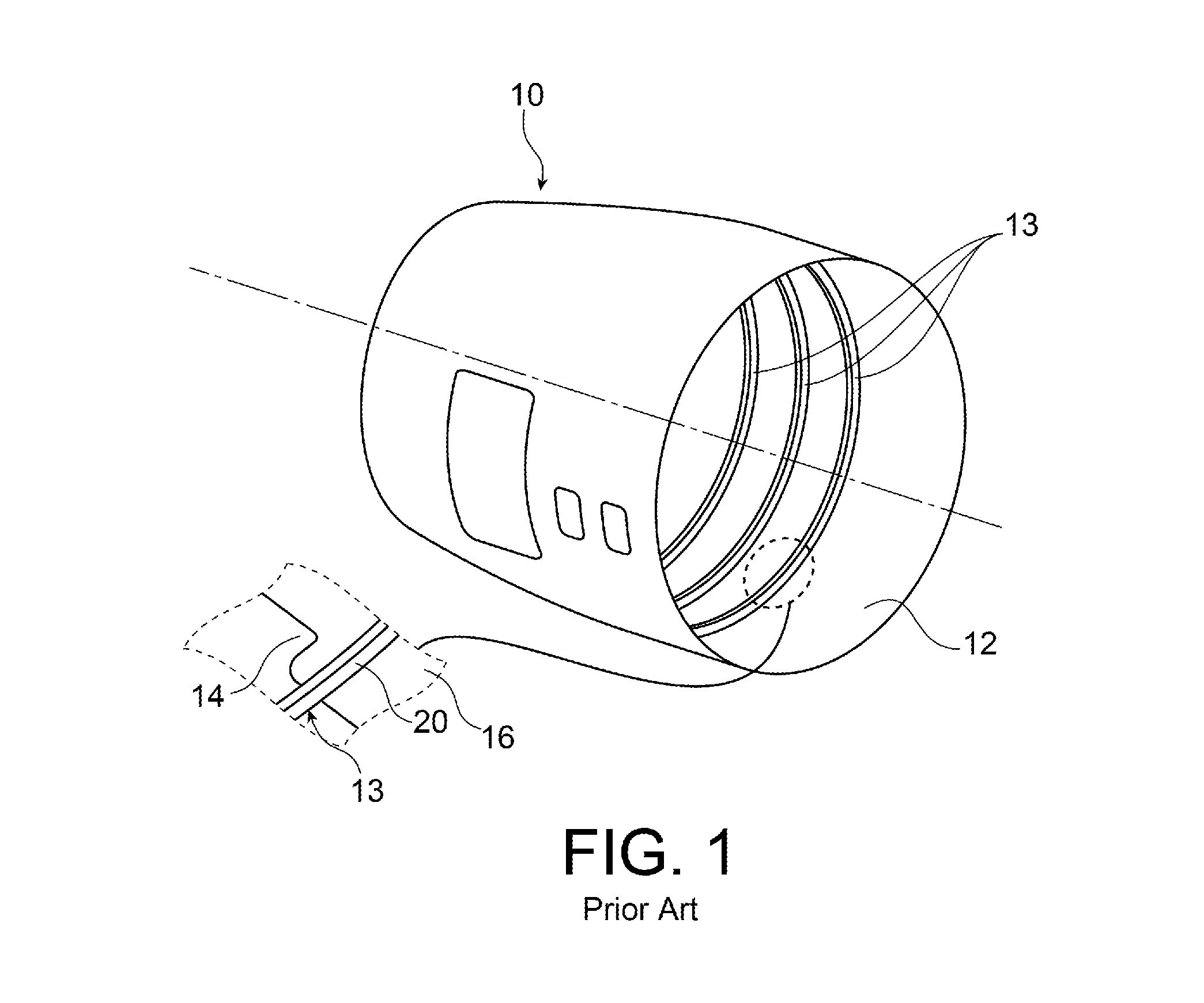
[0043]As in the example of FIG. 1 described above, the fuselage skin 112 comprises regions of different thicknesses, suited to local variations of the force level that the fuselage skin 112 has to withstand.

[0044]FIG. 6 represents a portion of the fu...


PUM


Abstract

In a fuselage portion for an aircraft, in order to reduce the assembly clearance between the soleplate of a circumferential frame and a fuselage skin in composite material while limiting the mass of the fuselage portion, a ply drop-off is used comprising two portions oriented in the circumferential direction and having different respective slopes.

Description

CROSS-REFERENCES TO RELATED APPLICATIONS[0001]This application claims the benefit of the French patent application No. 13 61524 filed on Nov. 22, 2013, the entire disclosures of which are incorporated herein by way of reference.BACKGROUND OF THE INVENTION[0002]The present invention relates to the field of aircraft fuselages made of composite material.[0003]It relates to a fuselage portion for an aircraft, such as a forward section in particular, in which the circumferential frames each have a soleplate applied continuously onto the fuselage skin. Such circumferential frames are commonly called “integral frames.”[0004]The invention is particularly advantageously applicable in the case of a forward section without stringers.[0005]One difficulty encountered in the production of aircraft fuselages lies in the operation of assembling the circumferential frames with the fuselage skin in the case where the circumferential frames each have a soleplate in contact with the fuselage skin.[0006...

Claims


Application Information

Patent Timeline
IPC IPC(8): B64C1/00
CPCB64C2001/0072B64C1/00B64C1/069Y10T428/24479Y02T50/40
Inventor BERNADET, PHILIPPEDELAHAYE, ROMAIN
Owner AIRBUS OPERATIONS SAS
Why Eureka
Try Eureka