
Latency tolerant fault isolation

a technology of maintenance data system and fault isolation, applied in the field of maintenance data system latency tolerance, can solve problems such as sensor error, actuator fault, electrical connector issue,

Inactive Publication Date: 2015-05-28
SIKORSKY AIRCRAFT CORP
View PDF20 Cites 6 Cited by
  • Summary
  • Abstract
  • Description
  • Claims
  • Application Information

AI Technical Summary

Benefits of technology

This patent describes a method and system for identifying and isolating faults in a computer network. The system receives evidence of a test failure and uses metadata to identify a potential system failure mode associated with the evidence. It then determines a maximum predicted latency for receiving the potential evidence associated with the failure mode. The system waits up to the maximum predicted latency to receive any additional evidence that may confirm the failure mode. Using this evidence and additional data, the system diagnoses the failure mode as a fault. The technical effect of this invention is that it allows for faster identification and isolation of network faults, which can improve operational efficiency and prevent downtime or data loss.

Problems solved by technology

A complex system can involve many subsystems which may have individual failure modes and cross-subsystem failure modes.
Simple fault identification provided by built-in tests can be helpful in identifying localized issues but may also represent symptoms of larger-scale issues that involve other subsystems or components.
For example, detecting a temperature fault in a hydraulic line could result from a sensor error, an electrical connector issue, a hydraulic fluid leak, environmental factors, an actuator fault, or other factors.
Isolating and identifying the most likely source of a fault and associated maintenance actions to address the fault can be challenging in a complex system, particularly when performed as a real-time process.

Method used


Image

  • Latency tolerant fault isolation
  • Latency tolerant fault isolation
  • Latency tolerant fault isolation

Examples


Embodiment Construction

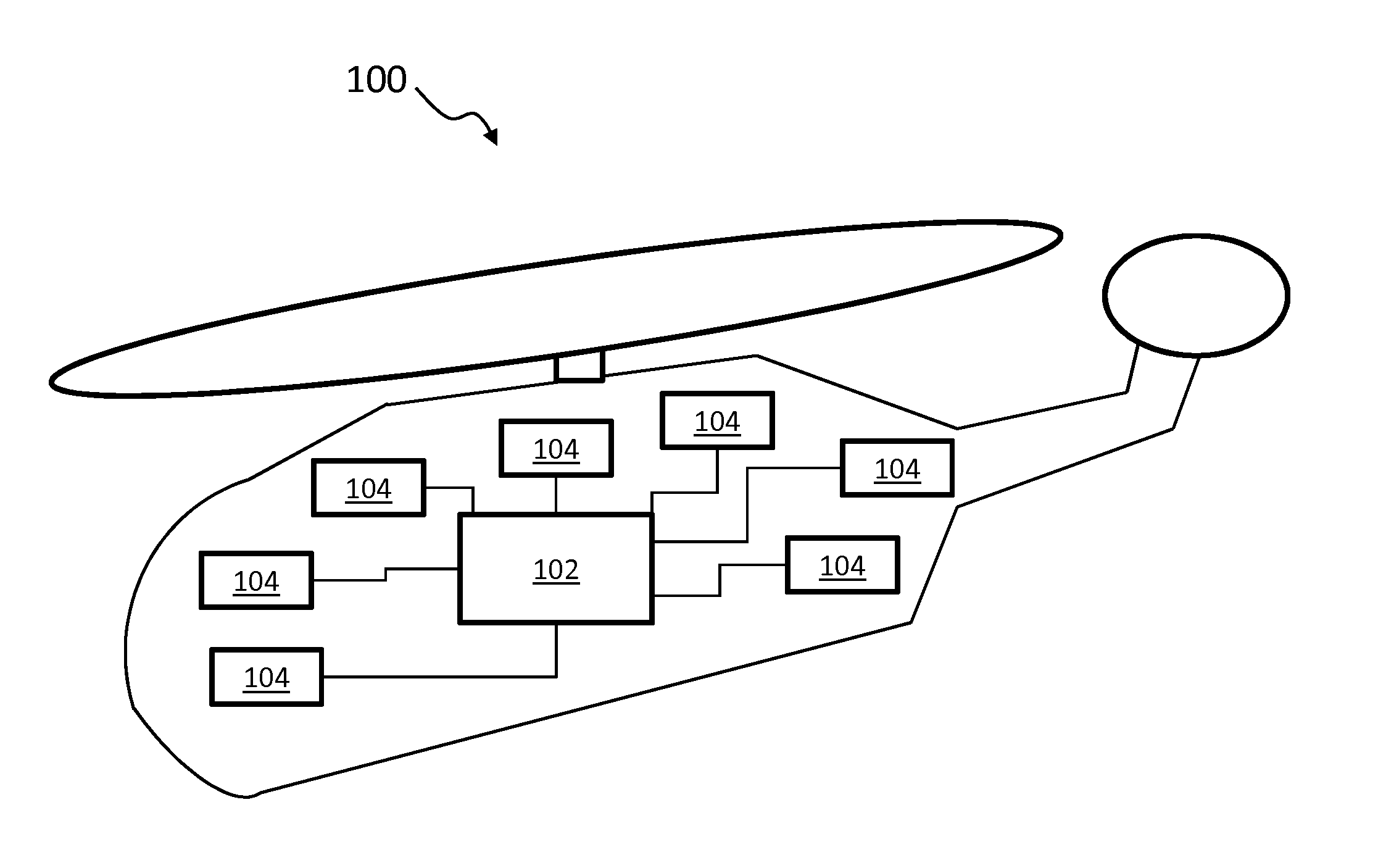
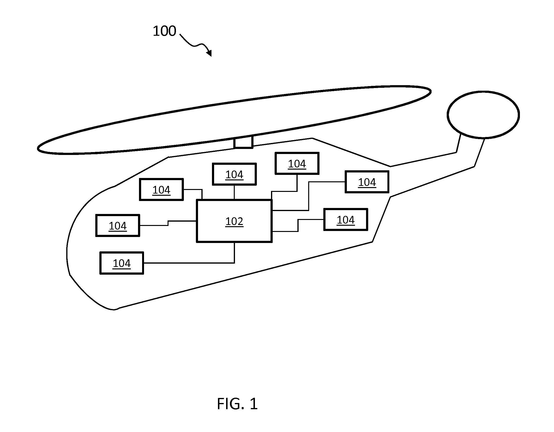
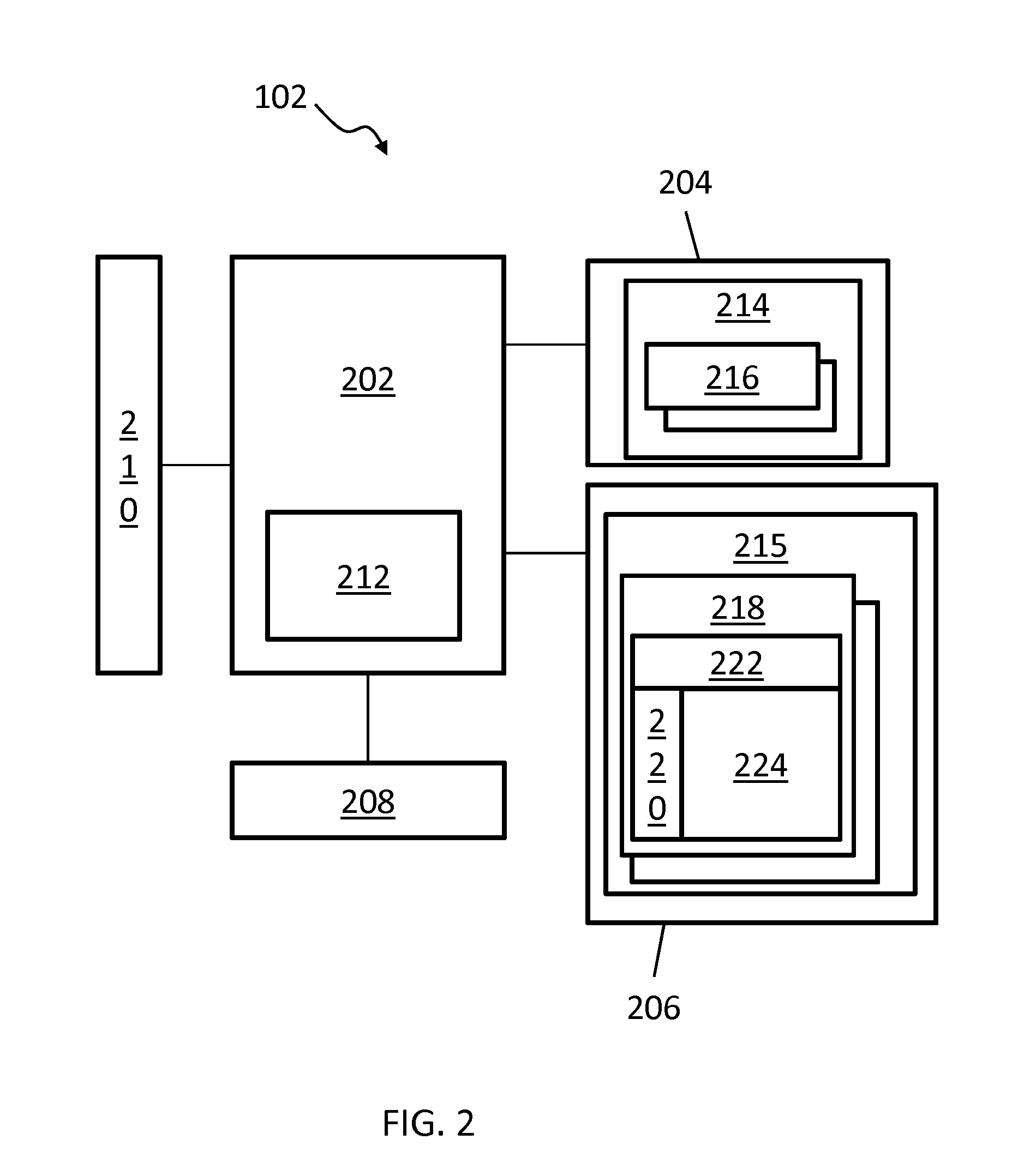
[0014]In exemplary embodiments, a dependency model bigraph metadata model is used to identify relationships between evidence provided by monitored subsystems and potential system failure modes. The evidence may be provided by built-in tests which can run over a period of time. In order to diagnose a system failure mode as a fault, multiple pieces of evidence may be needed. Each piece of evidence may not arrive at the same time, as some failures are rapidly detected, while others have greater latency. Rather than simply looking at test results for other related failures upon identifying a failure, embodiments analyze an associated dependency matrix to determine a maximum predicted latency from the failure to additional evidence generation. A weighted bigraph can be traversed to allow all applicable latencies to elapse prior to a failure resolution decision. Once a sufficient period of time has elapsed for all potential evidence to be received, a maintenance decision can be made with ...


PUM


Abstract

A method of latency tolerant fault isolation is provided. The method includes receiving, by a maintenance data computer, evidence associated with a test failure. The maintenance data computer accesses metadata to identify a system failure mode associated with the evidence and other potential evidence associated with the system failure mode. The maintenance data computer determines a maximum predicted latency to receive the potential evidence associated with the system failure mode based on the metadata. The method also includes waiting up to the maximum predicted latency to determine whether one or more instances of the potential evidence associated with the system failure mode are received as additional evidence. The maintenance data computer diagnoses the system failure mode as a fault based on the evidence and the additional evidence.

Description

GOVERNMENT RIGHTS[0001]This invention was made with government support under contract number N00019-06-C-0061 awarded by the United States Navy. The government has certain rights in the invention.BACKGROUND OF THE INVENTION[0002]The subject matter disclosed herein relates to maintenance data systems, and in particular to latency tolerant fault isolation in a maintenance data system.[0003]Real-time health or maintenance monitoring in a complex system can involve monitoring thousands of inputs as evidence of a potential fault or maintenance issue. A complex system can involve many subsystems which may have individual failure modes and cross-subsystem failure modes. Simple fault identification provided by built-in tests can be helpful in identifying localized issues but may also represent symptoms of larger-scale issues that involve other subsystems or components. For example, detecting a temperature fault in a hydraulic line could result from a sensor error, an electrical connector is...

Claims


Application Information

Patent Timeline
Patent Type & Authority Applications(United States)
IPC IPC(8): G07C5/00
CPCG07C5/00G07C5/0808G05B23/0283G06Q10/20
Inventor MAGSON, JAMES S.
Owner SIKORSKY AIRCRAFT CORP
Learn More