Cleaning apparatus

Active Publication Date: 2015-06-04
DISCO CORP
View PDF4 Cites 5 Cited by
  • Summary
  • Abstract
  • Description
  • Claims
  • Application Information

AI Technical Summary

Benefits of technology

The present invention provides a cleaning apparatus that prevents the cleaning fluid from scattering to the workpiece and sticking to it. This is achieved by using a water film forming nozzle to form a conical water film around the cleaning fluid sprayed from the nozzle, which prevents the mist of cleaning fluid from scattering outside the enclosure. The cleaning fluid is thus enclosed and suppressed from scattering, resulting in improved efficiency of the cleaning process.

Problems solved by technology

In the cleaning apparatus mentioned above, however, the cleaning fluid is sprayed under a very high pressure, so that the cleaning fluid collides with the workpiece to scatter in the form of a mist.
Accordingly, if the cleaning fluid scattering in the form of a mist sticks to the workpiece in a region already cleaned, this already cleaned region of the workpiece may be contaminated again with the foreign matter.
However, there is a problem such that the sticking of the cleaning fluid scattering in the form of a mist to the workpiece cannot be sufficiently prevented by only this exhaust opening.

Method used


Image

  • Cleaning apparatus
  • Cleaning apparatus
  • Cleaning apparatus

Examples


Embodiment Construction

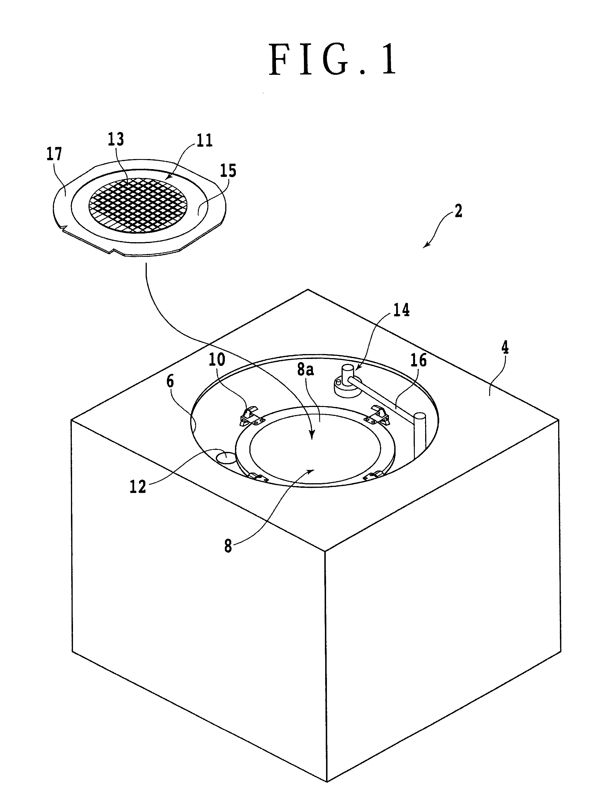
[0015]A preferred embodiment of the present invention will now be described with reference to the attached drawings. FIG. 1 is a perspective view schematically showing the configuration of a cleaning apparatus 2 according to this preferred embodiment. In FIG. 1, there is also shown a workpiece 11 to be cleaned by the cleaning apparatus 2. As shown in FIG. 1, the cleaning apparatus 2 includes a base 4 and a chamber 6 formed as a cylindrical space inside the base 4 so as to open to the upper surface of the base 4. A disk-shaped chuck table (spinner table) 8 for holding the workpiece 11 under suction is rotatably provided in the chamber 6. Four clamps 10 for fixing an annular frame 17 supporting the workpiece 11 are mounted on the periphery of the chuck table 8. That is, in the condition where the workpiece 11 supported by the annular frame 17 is held on the chuck table 8, the annular frame 17 is fixed at four positions by the four clamps 10.

[0016]For example, the workpiece 11 is a dis...


PUM


Abstract

Apparatus for cleaning a workpiece to remove foreign matter sticking to the workpiece includes a chuck table having a holding surface for holding the workpiece and a cleaning unit provided so as to face the workpiece for spraying a cleaning fluid to clean the workpiece. The cleaning unit includes a cleaning nozzle having a nozzle hole for spraying the cleaning fluid toward the workpiece, and a water film forming nozzle having an annular slit formed so as to surround the nozzle hole of the cleaning nozzle. The annular slit sprays the cleaning fluid in the form of a film having a conical shape, and extends from the annular slit to the workpiece held on the chuck table. The cleaning fluid sprayed from the nozzle hole of the cleaning nozzle has a columnar shape surrounded by the cleaning fluid sprayed from the annular slit of the water film forming nozzle.

Description

BACKGROUND OF THE INVENTION[0001]1. Field of the Invention[0002]The present invention relates to a cleaning apparatus for cleaning a platelike workpiece such as a semiconductor wafer.[0003]2. Description of the Related Art[0004]A platelike workpiece such as a semiconductor wafer having a plurality of devices such as ICs formed on the front side is cut along division lines (streets), thereby dividing the workpiece into a plurality of chips corresponding to the plural devices. The workpiece processed by such cutting (dicing) is contaminated with foreign matter such as cut dust and it is therefore cleaned by a cleaning apparatus to remove this foreign matter.[0005]The cleaning apparatus for cleaning the workpiece includes a chamber for defining a cleaning space, a rotatable chuck table for holding the workpiece in the chamber under suction, and a cleaning nozzle for spraying a cleaning fluid toward the workpiece from the upper side thereof (see Japanese Patent Laid-Open No. 2011-243833...

Claims


Application Information

Patent Timeline
IPC IPC(8): B08B3/04H01L21/02
CPCH01L21/02041B08B3/04B08B3/02H01L21/02076H01L21/67051
Inventor YUNFENG, YANGYAMADA, SHOJIRO
Owner DISCO CORP
Why Eureka
Try Eureka