Connection arrangement and structure

a technology of connection arrangement and connection structure, which is applied in the direction of shock absorbers, mechanical equipment, transportation and packaging, etc., can solve the problems of total failure of the entire structural connection, hole-bearing failure in a spatial orientation, and very significant weight increase of absorbers in the entire primary structure of aircraft, so as to achieve safe initiatable, high energy absorption capacity, and considerable energy absorption

Active Publication Date: 2015-06-04
AIRBUS OPERATIONS GMBH
View PDF0 Cites 4 Cited by
  • Summary
  • Abstract
  • Description
  • Claims
  • Application Information

AI Technical Summary

Benefits of technology

[0007]It is thus an object of the invention to create a largely weight-neutral connection arrangement for joining in particular at least two composite-fiber-reinforced components, for example CFRP-components, which connection arrangement, comprises a safely initiatable and adequately high energy absorption capacity that is reliably controllable in all phases for absorbing extreme mechanical loads, as can, for example, occur in the case of a crash of an aircraft. Furthermore, it is an object of the invention to create a structure comprising at least two joined components, which structure in the case of overload provides very considerable energy absorption.

Problems solved by technology

However, such crash absorbers very considerably increase the weight and the complexity of the entire primary structure of the aircraft.
However, in this context, generating a robust process of hole-bearing failure, which process at the same time can be reliably initiated and flows in a controlled manner, creates difficulties.
Furthermore, as a rule, in conventional rivet connections and / or bolt connections, hole-bearing failure occurs in a spatial orientation that is determined by the angle of the lowest laminate strength and by the angles of the direction of the load application.
Moreover, in the case of conventional rivet connections and / or bolt connections there is the danger of the so-called head-pull resistance and associated with it the total failure of the entire structural connection.
Furthermore, there is the possibility of an uncontrolled increase in force as a result of jammed or blocked fragments or displaced laminate.
This device is associated with a disadvantage in that an additional component is required in order to, in the case of a crash, convert the movement energy to some other form of energy, and consequently the weight and the complexity of the structure are increased.

Method used


Image

  • Connection arrangement and structure
  • Connection arrangement and structure
  • Connection arrangement and structure

Examples


Embodiment Construction

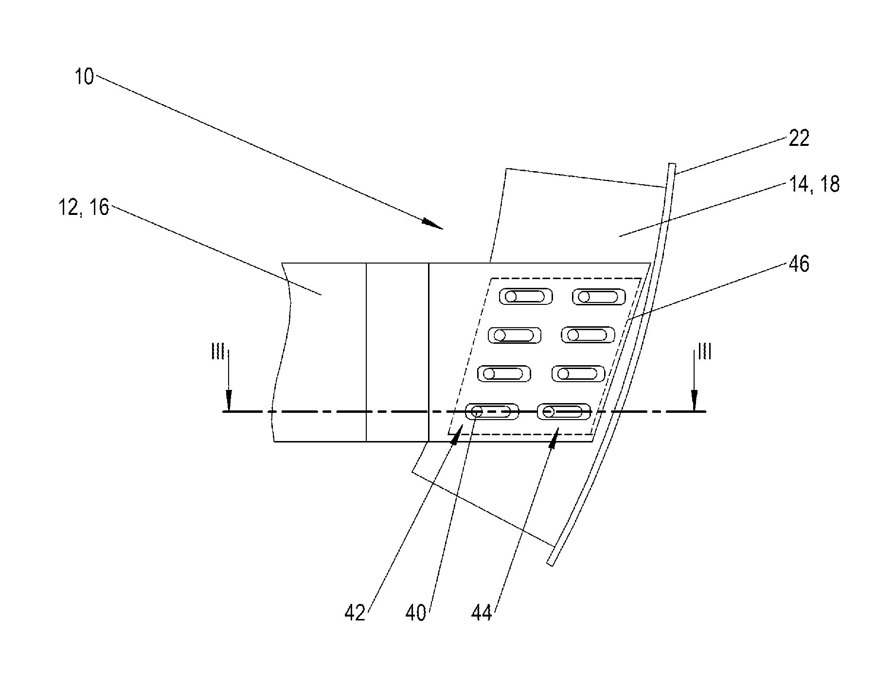
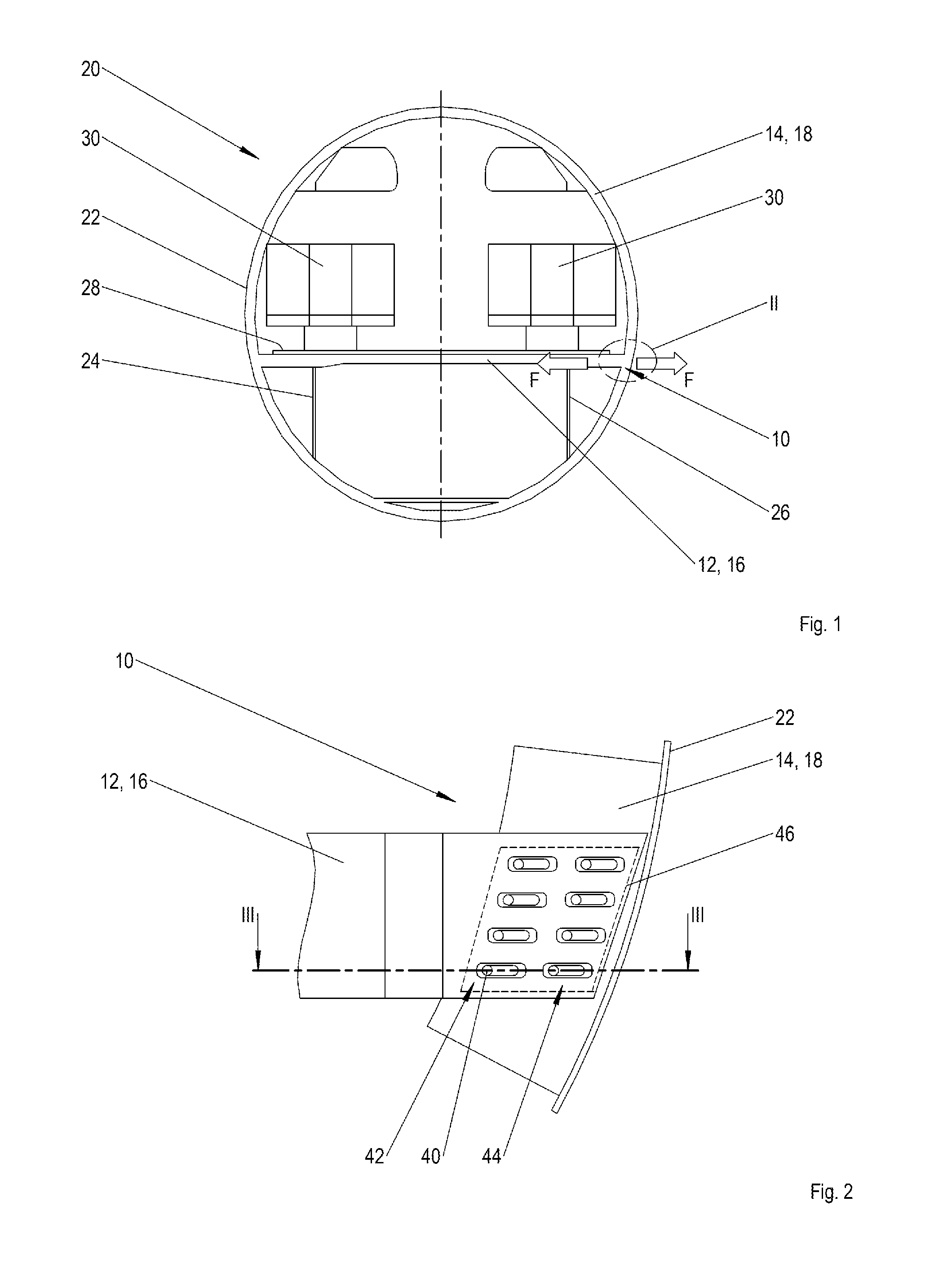
[0044]FIG. 1 shows a diagrammatic cross-sectional view of a fuselage cell structure of an aircraft with a connection arrangement according an embodiment of to the invention.

[0045]By means of an energy-absorbing and thus largely crash-safe connection arrangement 10 a first and a second component 12, 14 are interconnected, which components 12, 14 in the diagram purely as an example are a transverse member 16 and a circular frame element 18 of a fuselage cell 20 of an aircraft (not shown). On the outside the circular frame element 18 comprises a fuselage cell skin 22, and the transverse member 16 together with two vertical struts 24, 26 is used to support a floor 28 on which several passenger seats 30 are arranged in rows.

[0046]In the case of a heavy crash, e.g., when the fuselage cell 20 hits a runway without the landing gear extended, or in the case of some other rapid mechanical deceleration of the fuselage cell 20, very substantial forces F act among other things on the transverse ...


PUM


Abstract

An energy-absorbing connection arrangement with a multitude of connectors for joining two components, such as a transverse member and a circular frame element, of an aircraft fuselage. Each connector comprises a headed shaft and the shafts reach through component boreholes. On the shaft ends facing away from the heads, counter-bearings are provided. At least one of the components comprises a fiber-reinforced plastic material. A head and/or counter-bearing of at least one connector rests against at least one underlay device. The underlay device is received in a guide groove in the first component, with the guide groove commencing in the region of the boreholes. The underlay device, upon exceeding a mechanical threshold load, is slidable away from the boreholes. Energy absorption takes place along a longitudinal center axis of the guide groove as a result of hole-bearing-stress failure and/or the shearing of the fiber-reinforced plastic material component.

Description

CROSS-REFERENCES TO RELATED APPLICATIONS[0001]This application claims the benefit of the German patent application No. 10 2013 113 393.2 filed on Dec. 3, 2013, the entire disclosures of which are incorporated herein by way of reference.BACKGROUND OF THE INVENTION[0002]The invention relates to an energy-absorbing connection arrangement for joining at least two components, in particular a transverse member and a circular frame element of a fuselage cell structure of an aircraft wherein the connection arrangement comprises a multitude of connectors that are, in particular, arranged in a matrix-like manner, wherein each connector comprises a head with a shaft, and the shafts reach through associated boreholes in the components, and on the shaft ends facing away from the heads in each case counter-bearings are provided, and a first component comprising a fiber-reinforced plastic material and at least one further component comprising a metallic material and / or comprising a fiber-reinforce...

Claims


Application Information

Patent Timeline
Patent Type & Authority Applications(United States)
IPC IPC(8): B64C1/06
CPCB64C1/062B64C1/18F16F7/08F16F7/124F16F7/127
Inventor HACHENBERG, DIETERMARGULL, LARSKOHLGRUEBER, DIETERWAIMER, MATTHIASKRAFT, HARALD
Owner AIRBUS OPERATIONS GMBH
Why Eureka
Try Eureka