
Tethered Vehicle Control and Tracking System

a technology of vehicle control and tracking system, which is applied in the direction of process control, electric generator control, instruments, etc., can solve the problems of increasing system cost, increasing system cost, and affecting the safety of kite control systems,

Active Publication Date: 2015-06-04
NASA
View PDF8 Cites 14 Cited by
  • Summary
  • Abstract
  • Description
  • Claims
  • Application Information

AI Technical Summary

Benefits of technology

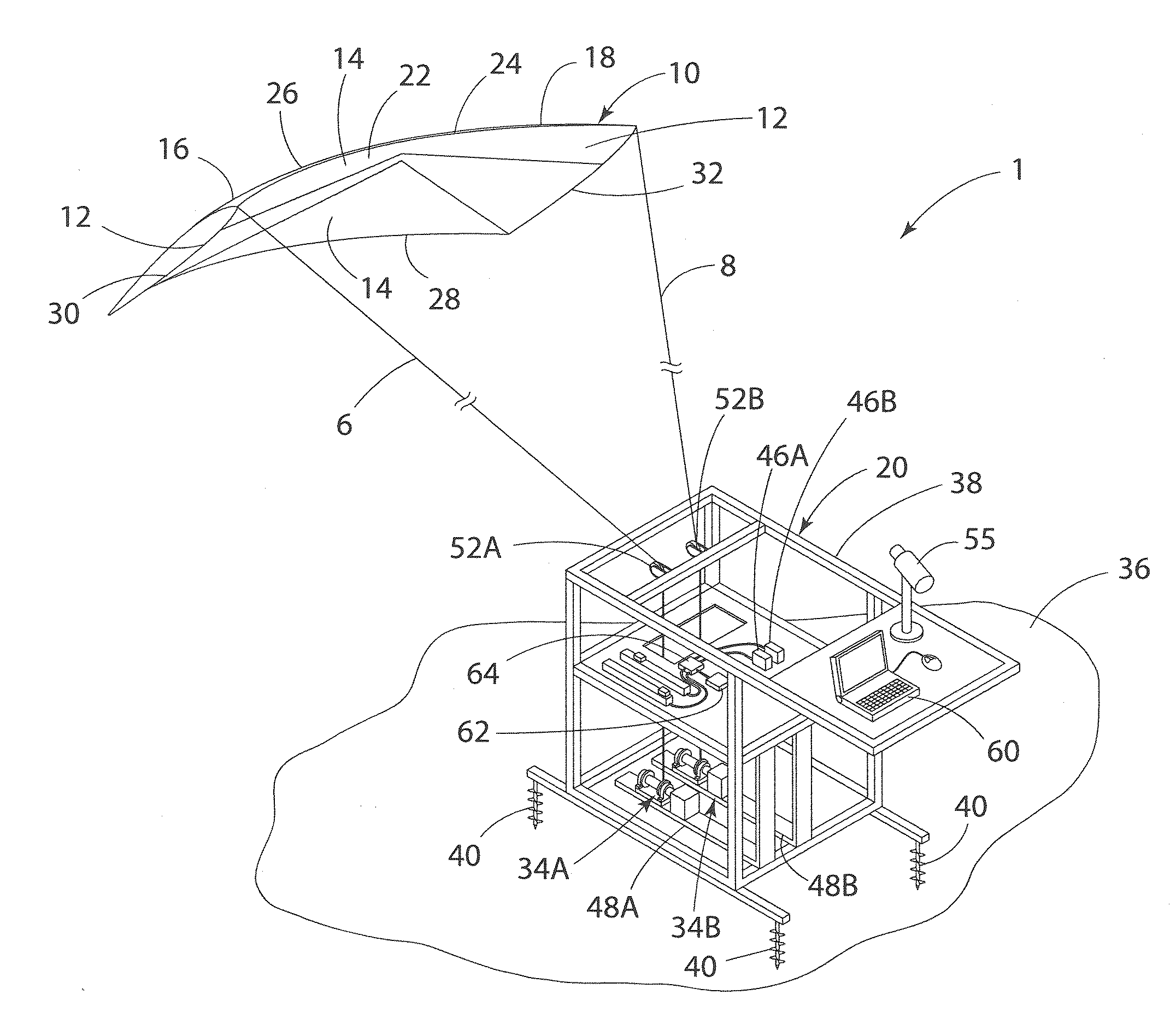
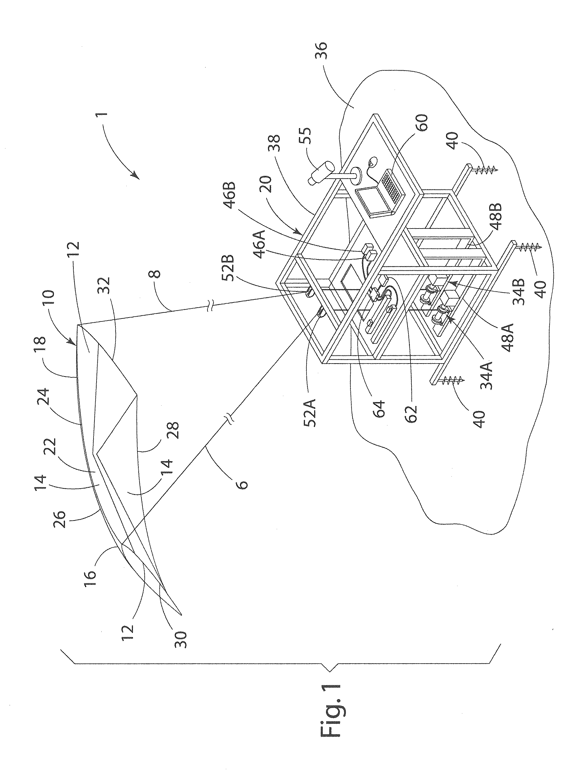
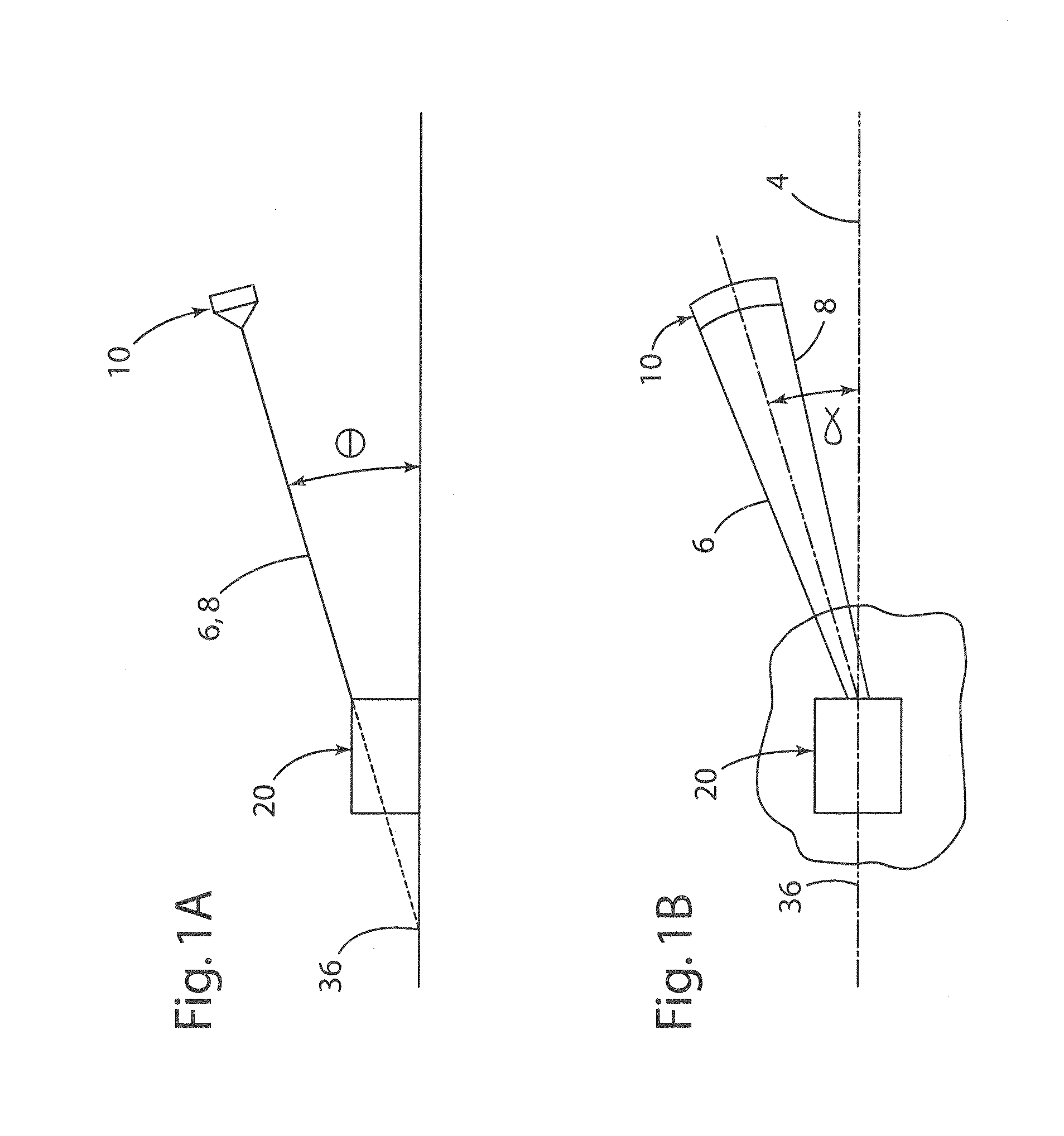
The present invention is a kite system for generating power. The system includes a kite and two lines connected to it. The system also includes two powered winding members that reel in the lines if they are actuated. The system uses a fuzzy logic control system to determine the kite's position and velocity relative to a base. The controller uses this information to control the movement of the winding members, which causes the kite to fly in a crosswind trajectory and generate power. The system can also include a camera and image processing system to determine the kite's position. The technical effects of the invention include improved control of the kite's movements and efficient power generation.

Problems solved by technology

Since the kite (which may resemble a glider aircraft) and its payload are relatively expensive, it is necessary to develop a sufficiently reliable control system to prevent crash landings.
These components further increase the cost of the system.
However, known kite control systems suffer from various drawbacks.

Method used


Image

  • Tethered Vehicle Control and Tracking System
  • Tethered Vehicle Control and Tracking System
  • Tethered Vehicle Control and Tracking System

Examples


Embodiment Construction

[0045]For purposes of description herein, the terms “upper,”“lower,”“right,”“left,”“rear,”“front,”“vertical,”“horizontal,” and derivatives thereof shall relate to the invention as oriented in FIG. 1. However, it is to be understood that the invention may assume various alternative orientations and step sequences, except where expressly specified to the contrary. It is also to be understood that the specific devices and processes illustrated in the attached drawings, and described in the following specification, are simply exemplary embodiments of the inventive concepts defined in the appended claims. Hence, specific dimensions and other physical characteristics relating to the embodiments disclosed herein are not to be considered as limiting, unless the claims expressly state otherwise.

[0046]AWE systems are normally more effective if the kite is flown in a high-speed crosswind trajectory. A crosswind trajectory increases the tension on the lines, thereby providing for power generati...


PUM


Abstract

A kite system includes a kite and a ground station. The ground station includes a sensor that can be utilized to determine an angular position and velocity of the kite relative to the ground station. A controller utilizes a fuzzy logic control system to autonomously fly the kite. The system may include a ground station having powered winding units that generate power as the lines to the kite are unreeled. The control system may be configured to fly the kite in a crosswind trajectory to increase line tension for power generation. The sensors for determining the position of the kite are preferably ground-based.

Description

CROSS-REFERENCE TO RELATED PATENT APPLICATION[0001]This patent application is a continuation of and claims the benefit of priority to U.S. patent application Ser. No. 13 / 765,714, filed on Feb. 13, 2013, which claims the benefit of and priority to U.S. Provisional Patent Application No. 61 / 709,187, filed on Oct. 3, 2012, the contents of which are hereby incorporated by reference in their entirety.STATEMENT REGARDING FEDERALLY SPONSORED RESEARCH OR DEVELOPMENT[0002]The invention described herein was made in part by an employee of the United States Government and may be manufactured and used by or for the Government of the United States of America for governmental purposes without the payment of any royalties thereon or therefore.BACKGROUND OF THE INVENTION[0003]Airborne wind energy (AWE) generally refers to producing energy from wind using a tethered air vehicle (i.e. a kite). A system of this type has a significant advantage over ground based wind turbines because it can take advanta...

Claims


Application Information

Patent Timeline
Patent Type & Authority Applications(United States)
IPC IPC(8): G05D1/10F03D7/00F03D9/00
CPCG05D1/105F03D7/00F03D9/002B64C31/06F05B2270/707F03D5/06Y02E10/70G05D1/0866F03D9/25Y02E10/72G05D1/08
Inventor NORTH, DAVID D.AULL, MARK J.
Owner NASA
Learn More