
Power tool

Active Publication Date: 2015-06-11
ATLAS COPCO INDAL TECHN
View PDF8 Cites 2 Cited by
  • Summary
  • Abstract
  • Description
  • Claims
  • Application Information

AI Technical Summary

Benefits of technology

The invention provides a solution for improving the sealing and lubrication of a power tool's bevel gear by continuously providing lubrication fluid to the sealing through a fluid tight housing. This prevents burning and maintains the sealing's function throughout its lifetime. Compared to conventional solutions, this solution allows for optimal distribution of forces and mounting of the pinion shaft close to the pinion gear. The invention also includes a hollow support member that delimits the gear space and a at least one fluid conveying opening for the continuity of lubricant fluid. This results in improved performance and durability of the power tool.

Problems solved by technology

A problem that arises in conventional power tools of this type is that especially the axial sealing around the pinion shaft is degenerated over time, such that lubrication fluid may eventually leak into the motor room and / or pass out to the area known as the reception area, e.g. the area immediately surrounding the power tool and the operator.

Method used


Image

  • Power tool
  • Power tool
  • Power tool

Examples


Embodiment Construction

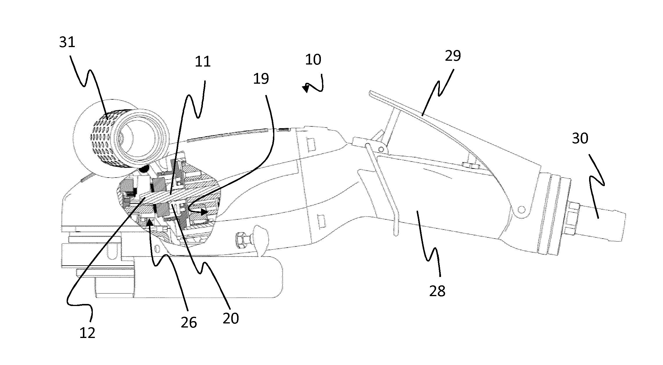
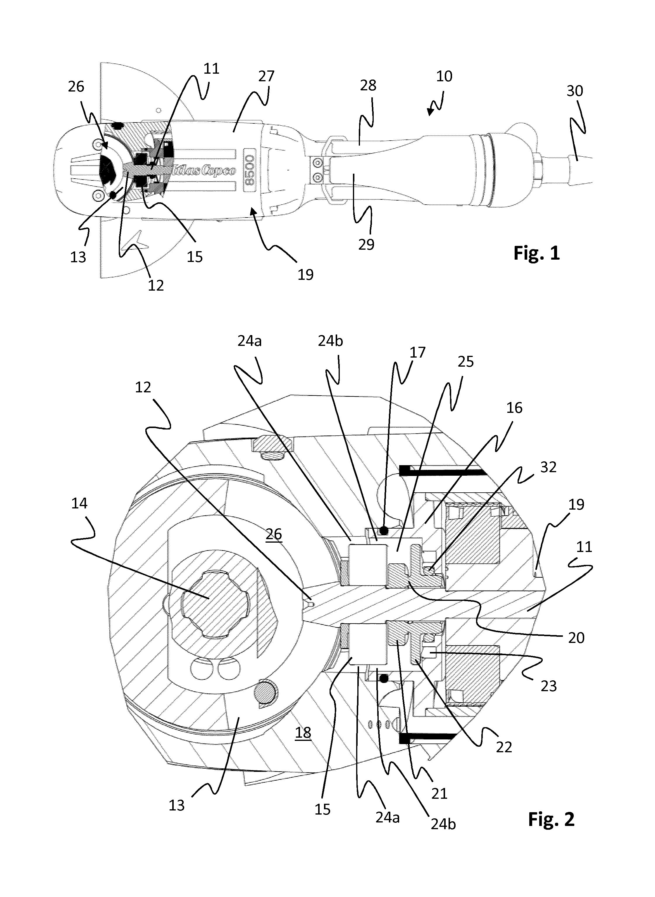
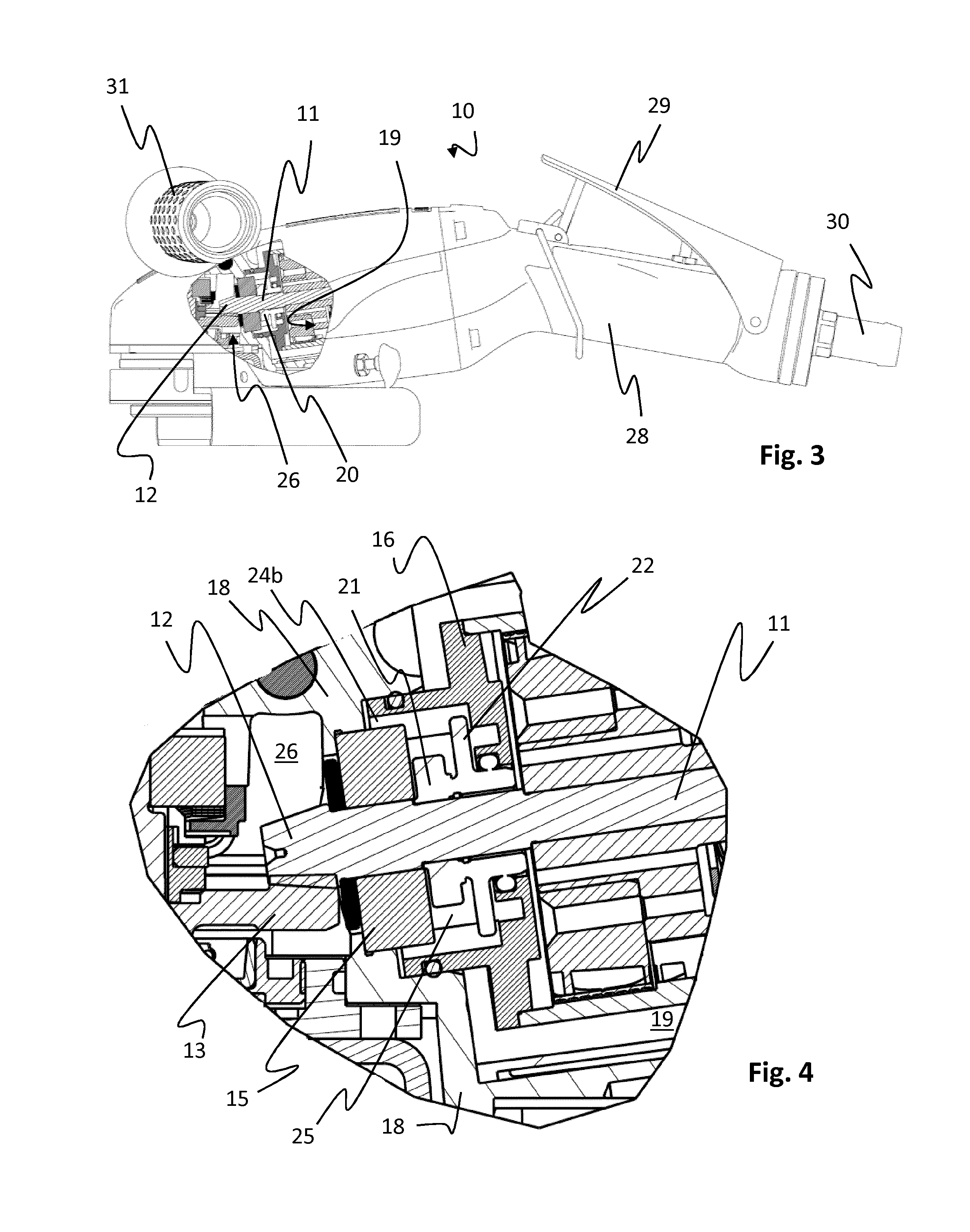
[0026]In FIG. 1 a power tool 10 according to a specific embodiment of the invention is shown. The power tool 10 comprises a motor room 19 and a gear space 26, which are housed in a common outer housing 27. Further the power tool 10 comprises a handle 28, on which a lever 29 is arranged for controlling the air supply to a motor arranged inside the motor room 19. The handle is connected to an air supply hose 30 for supply of pressurized air to the motor.

[0027]As is visible in the cut out section of FIG. 1 the gear space 26 includes a bevel gear 12, 13, in which a pinion shaft 11 is connected via a pinion gear 12 to a crown gear 13.

[0028]FIG. 2 shows a close up of the part of the power tool 10 to which the invention relates. A pinion shaft 11 is arranged to transmit the motor output from the motor inside a motor room 19 to the bevel gear 12, 13, which is located inside a gear housing 18 that delimits the gear space 26. The bevel gear comprises a pinion gear 12, which constitutes the en...


PUM


Abstract

A hand held power tool includes: a motor room housing a motor that drives an output shaft; a bevel gear including interconnected pinion and crown gears, wherein the pinion gear is connected to a pinion shaft drivingly connected to the output shaft and the crown gear is drivingly connected to a tool holding shaft; a gear housing that delimits a fluid tight gear space around the bevel gear; a bearing, around the pinion shaft and close to the pinion gear, which delimits a confined space around the pinion shaft and within the gear space; and a fluid tight axial sealing, around the pinion shaft inside the confined space of the gear space, which seals off the gear space from the motor room. At least one fluid conveying opening is arranged to put the confined space of the gear space in fluid contact with the rest of the gear space.

Description

[0001]The invention relates to a power tool such as a grinder. Specifically, the invention relates to a power tool with an improved fluid sealing arrangement between a gear space and a motor room.BACKGROUND[0002]A conventional power tool, such as e.g. a grinder, comprises a bevel gear that is provided to redirect the rotational movement from a pinion shaft rotating around a first axis to an output shaft rotating around a second axis that is substantially perpendicular to the first axis.[0003]The bevel gear is continuously in need of lubrication. In the type of power tool to which the invention relates this may be solved in that a lubrication fluid is arranged in a fluid tight gear space that surrounds the bevel gear. In order to prevent that the lubrication fluid leaks out from the gear space, the gear space is sealed off. Hence, the gear space is a fluid tight space that is delimited by a gear housing. The gear housing is normally formed of several parts and inter alia includes two...

Claims


Application Information

Patent Timeline
IPC IPC(8): B24B23/02B25F5/00B24B47/10
CPCB24B23/026B25F5/001B24B47/10
Inventor RADIF, NABIL KHALIL
Owner ATLAS COPCO INDAL TECHN
Learn More