
Crawler belt

a technology of crawler belt and track link, which is applied in the direction of endless track vehicles, metal chains, vehicles, etc., can solve the problems of large space required for keeping track links in storage, unstable storage state, and difficulty in stably stacking up track links, so as to improve transportation efficiency and stably stack track links for storage.

Inactive Publication Date: 2015-06-11
NIHON KENKI CO LTD
View PDF4 Cites 37 Cited by
  • Summary
  • Abstract
  • Description
  • Claims
  • Application Information

AI Technical Summary

Benefits of technology

The present invention provides a crawler belt that improves the efficiency of transportation and storage. This is achieved by incorporating a design that allows for stable stacking and fitting of track links during storage and transportation. This leads to a more compact and efficient use of space, reducing costs and facilitating logistical management.

Problems solved by technology

Therefore, it is difficult to stably stack up a plurality of track links at the time of putting the track links in storage or the like as it is.
Therefore, in a case of flatwise laying the respective track links individually, there is a problem that a large space is required for keeping them in storage.
On the other hand, in a case of storing each of the track links in a pallet to be stacked up for storage, the storage state becomes possibly an unstable style of packing.
In addition, since it is required to prepare pallets separately, there occurs a problem of a cost increase.

Method used


Image

  • Crawler belt
  • Crawler belt
  • Crawler belt

Examples


first embodiment

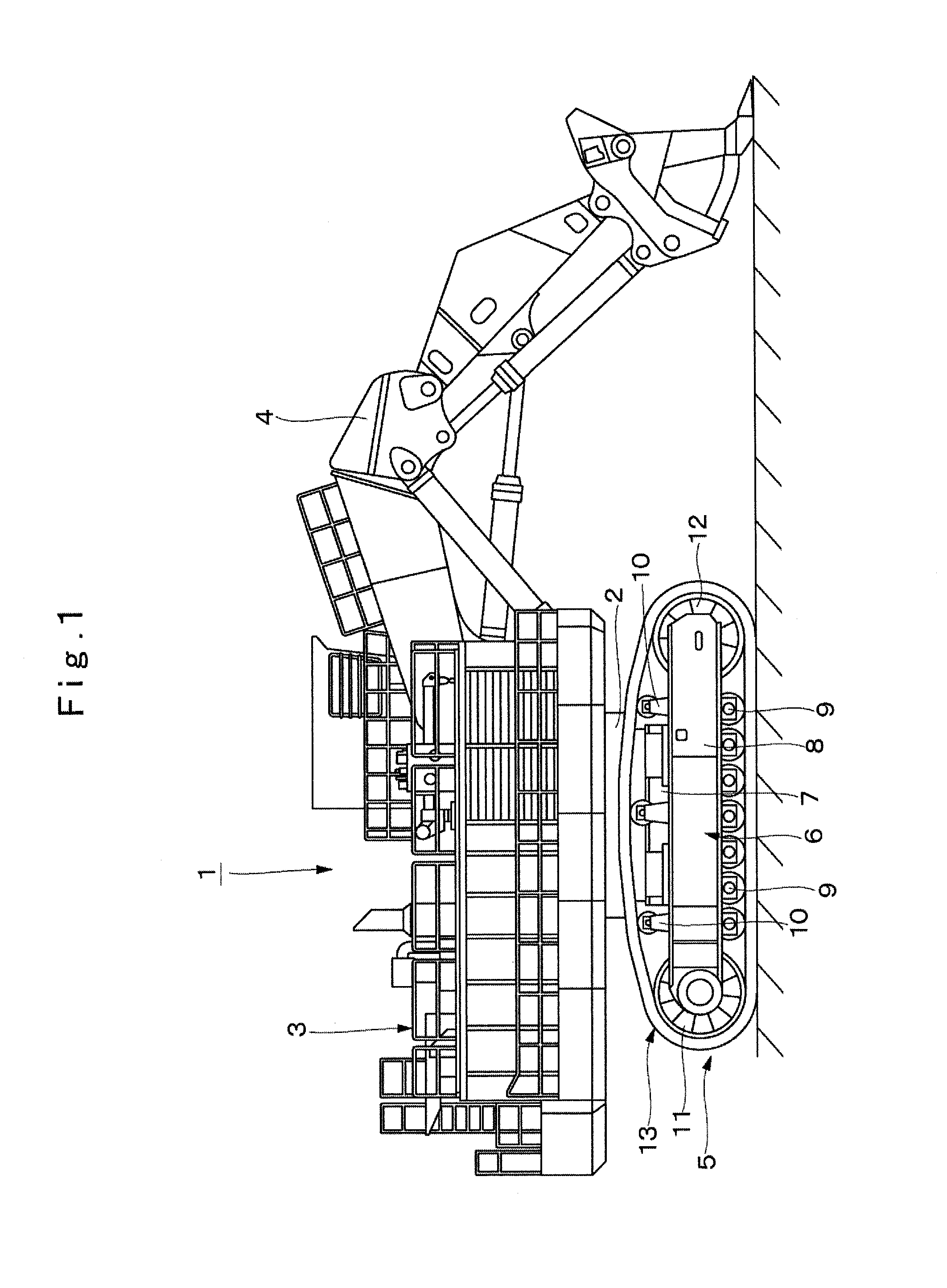
[0042]FIG. 1 to FIG. 11 show the present invention.

[0043]In FIG. 1, indicated at 1 is an extremely large-sized hydraulic excavator as a construction machine. The hydraulic excavator 1 comprises a lower traveling structure 5 to be described later, an upper revolving structure 3 that forms part of a vehicle body together with the lower traveling structure 5 and is revolvably mounted on the lower traveling structure 5 through a revolving ring 2, and a working mechanism 4 that is tiltably provided in the front side of the upper revolving structure 3 for performing an excavating operation of earth and sand, or the like.

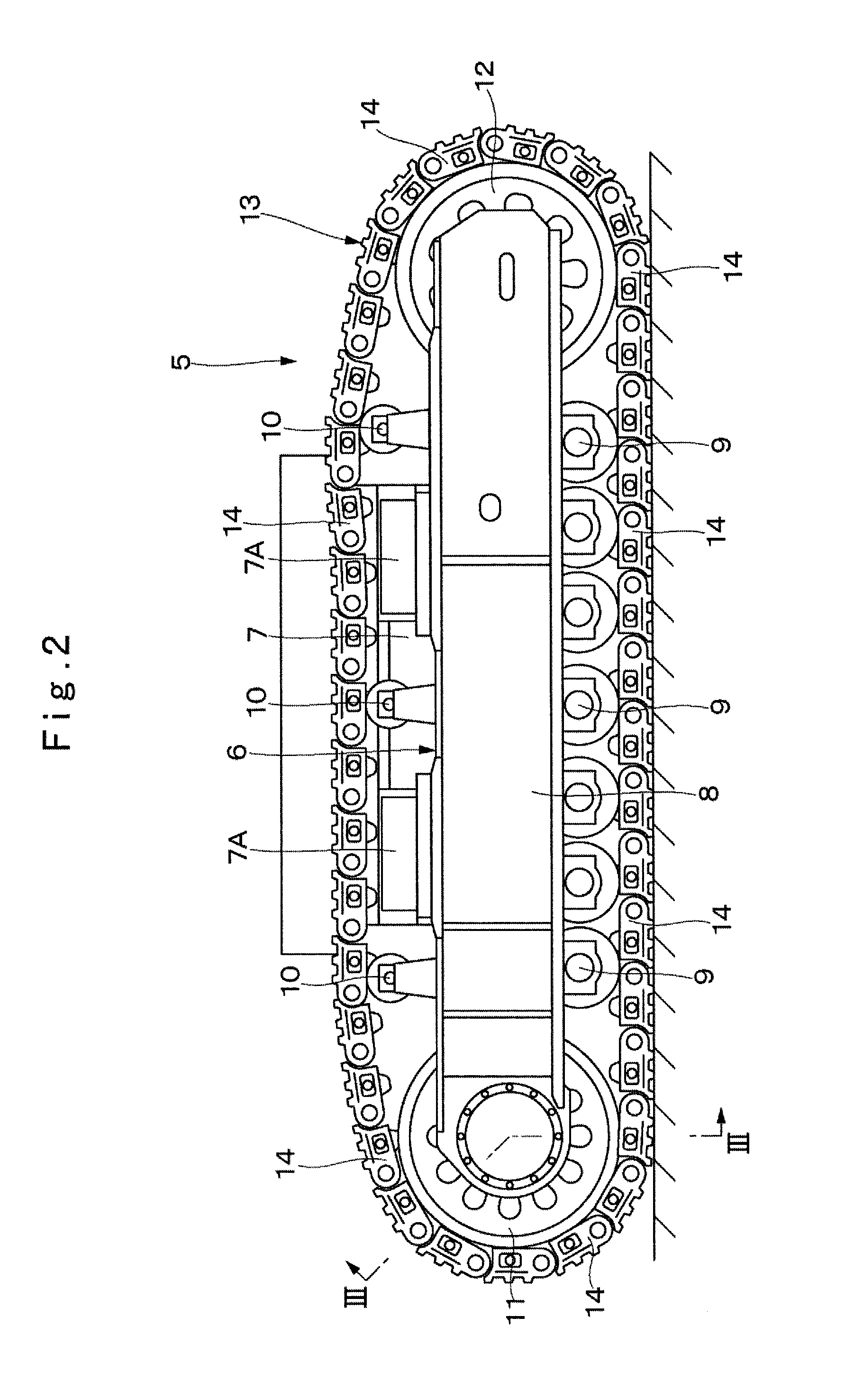
[0044]The crawler type lower traveling structure 5 is designed to stably travel on an uneven ground and a muddy ground. The lower traveling structure 5 comprises a truck frame 6, lower rollers 9, upper rollers 10, a drive wheel 11, an idler wheel 12, and a crawler belt 13, which will be described later.

[0045]The truck frame 6 comprises a center frame 7 that is positioned i...


PUM

PropertyMeasurementUnit
weightaaaaaaaaaa
width dimensionaaaaaaaaaa
length dimensionaaaaaaaaaa

Abstract

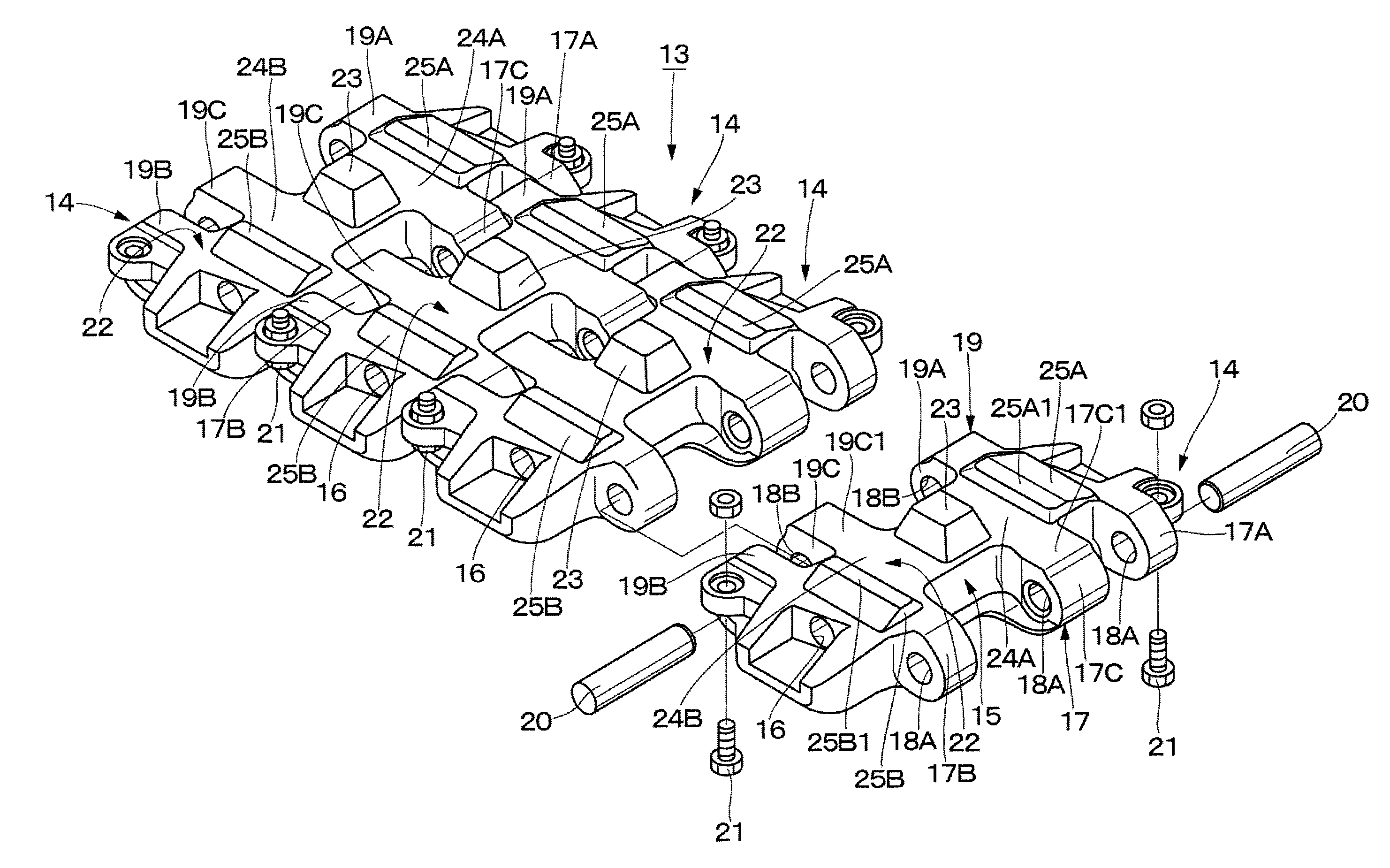
In each of track links (14) forming a crawler belt (13), an engaging projection (23) engaging to a drive wheel (11) is provided on a drive wheel abutting surface (22) abutting on the drive wheel (11). A fitting groove (27) composed of a bottomed recessed groove is provided on a ground contact surface (26) at the opposite side to the drive wheel abutting surface (22) in the upper-lower direction in a position corresponding to the engaging projection (23). Thereby, at the time of stacking up the track links (14) in the upper-lower direction, the fitting groove (27) of the upper track link (14) can be fitted into the engaging projection (23) of the lower track link (14).

Description

TECHNICAL FIELD[0001]The present invention relates to a crawler belt used in a crawler type vehicle, such as a hydraulic excavator, a hydraulic crane, or the like.BACKGROUND ART[0002]In general, a crawler type vehicle, such as a hydraulic excavator, a hydraulic crane, or the like, comprises an automotive lower traveling structure, an upper revolving structure that is revolvably mounted on the lower traveling structure, and a working mechanism that is mounted to the upper revolving structure.[0003]Here, for example, a lower traveling structure in a large-sized crawler type vehicle is configured of a truck frame including a center frame, and side frames that are provided at both sides of the center frame in the left-right direction to extend in the front-rear direction; a drive wheel that is provided on one side of each of the side frames in the truck frame in the length direction; an idler wheel that is provided on the other side of each of the side frames in the length direction; a ...

Claims


Application Information

Patent Timeline
Patent Type & Authority Applications(United States)
IPC IPC(8): B62D55/20B62D55/21
CPCB62D55/21B62D55/202B62D55/12B62D55/26B62D55/32
Inventor TAKAGI, TOSHIKATSUSUGIYAMA, YUKIHIKOKANEZAWA, HIROSHI
Owner NIHON KENKI CO LTD
Learn More