Micro-projection system

a technology of projection system and projection device, which is applied in the direction of printers, coupling device connections, instruments, etc., can solve the problem of enhancing the design cost of portable devices, and achieve the effect of increasing the commonality of thes

Inactive Publication Date: 2015-06-11
LITE ON TECH CORP
View PDF6 Cites 2 Cited by
  • Summary
  • Abstract
  • Description
  • Claims
  • Application Information

AI Technical Summary

Benefits of technology

[0007]The present invention provides a micro-projection system which increases the commonality thereof.

Problems solved by technology

However, the different portable device may use different design of the micro-projection system as the remaining space changes, such that the design cost of the portable device may be enhanced.

Method used


Image

  • Micro-projection system
  • Micro-projection system
  • Micro-projection system

Examples


Embodiment Construction

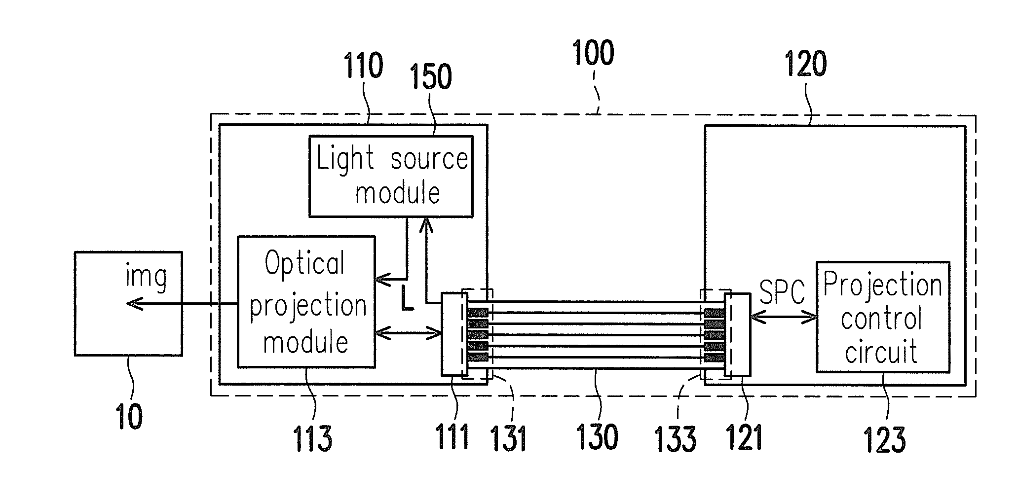
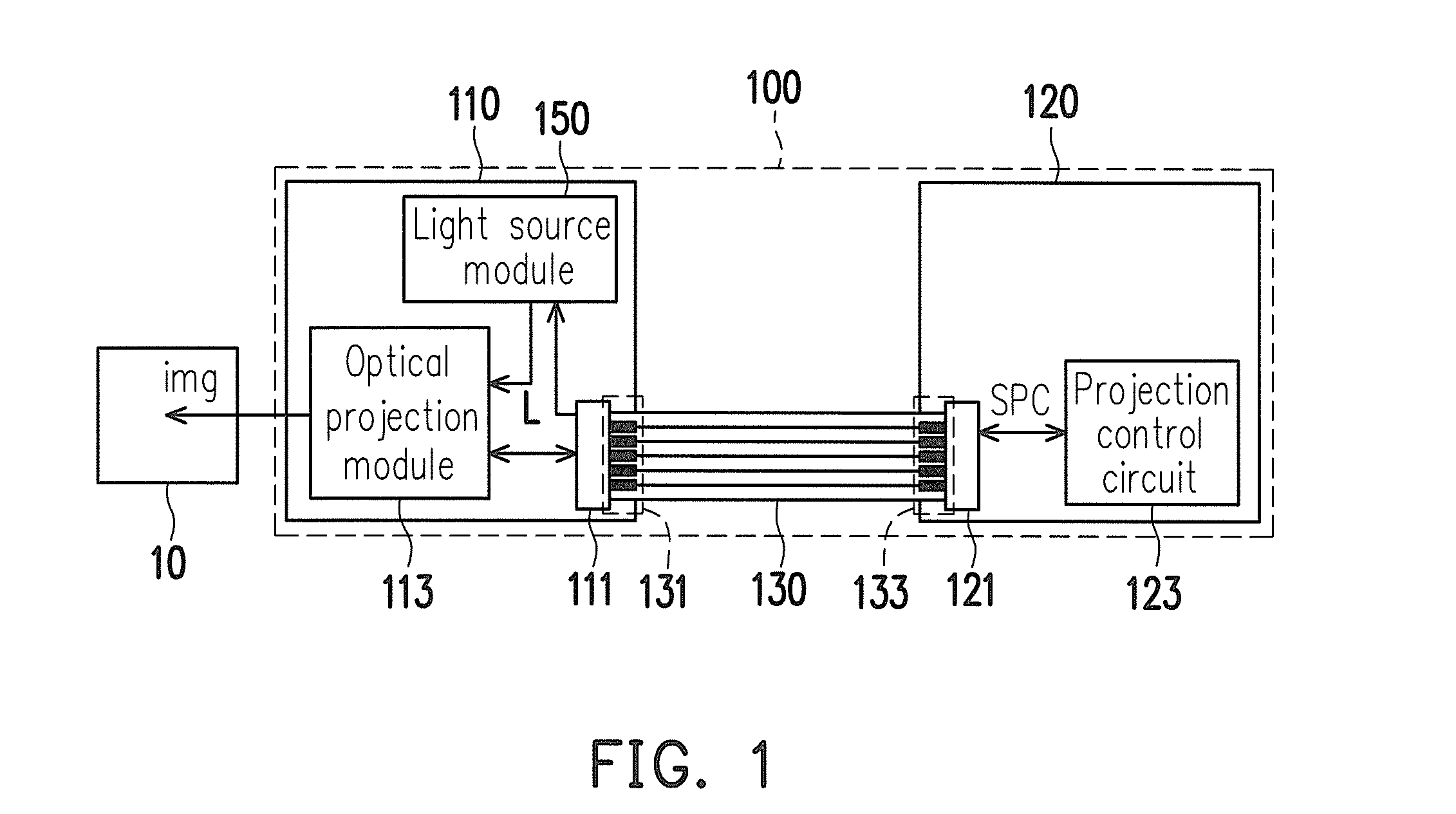
[0020]FIG. 1 is a system diagram illustrating a micro-projection system according to an embodiment of the present invention. Referring to FIG. 1, in the present embodiment, a micro-projection system 100 may be configured in a portable electronic device, and the micro-projection system 100 includes an optical engine 110, a control module 120, and a flat cable 130. The optical engine 110 is electrically connected to the control module 120 through the flat cable 130, and the flat cable 130 is detachably connected to the optical engine 110 and the control module 120 respectively. The control module 120 is configured to provide and transmit a plurality of control signals SPC to the optical engine 110 through the flat cable 130 to control the operation of the optical engine 110.

[0021]The optical engine 110 includes a light source module 150, an optical projection module 113, and a first connection port 111. The light source module 150 is configured to generate an image light beam to the o...


PUM


Abstract

A micro-projection system applied to a portable electronic device, comprising an optical engine, a control module, and a flat cable. The optical engine projects an image. The control module provides at least one control signal to control the optical engine. The flat cable is detachably connected to the optical engine and the control module respectively. Wherein, the optical engine and the control module are configured in the portable electronic device separately, and the flat cable has a corresponding configuration state for connecting the optical engine to the control module.

Description

CROSS-REFERENCE TO RELATED APPLICATION[0001]This application claims the priority benefit of China application serial no. 201310664049.2, filed on Dec. 9, 2013. The entirety of the above-mentioned patent application is hereby incorporated by reference herein and made a part of this specification.BACKGROUND OF THE INVENTION[0002]1. Field of the Invention[0003]The present invention generally relates to a micro-projection system, and in particular, to a micro-projection system which can be applied to portable devices.[0004]2. Description of Related Art[0005]The micro-projection technology is applied to a portable device with advantages of light weight and small volume, such as a projection technology applied to mobile phones, digital cameras, notebooks, etc. According to the display technology, the micro-projection technology is mainly divided into a liquid crystal display (LCD) technology, a digital light processing (DLP) display technology, a liquid crystal on silicon (LCOS) display t...

Claims


Application Information

Patent Timeline
Patent Type & Authority Applications(United States)
IPC IPC(8): G03B21/14G03B21/20
CPCG03B21/2053G03B21/145G03B29/00H01R12/78
Inventor HSU, CHENG-CHUNGTSAI, YU-NAN
Owner LITE ON TECH CORP
Why Eureka
Try Eureka