Method for changing the software in the memory of an electronic control unit

a technology of electronic control unit and software, applied in the field of changing the software in the memory of an electronic control unit, can solve the problems of many control units carrying out validity testing, cannot always be achieved, time-consuming,

Inactive Publication Date: 2015-06-11
DSPACE DIGITAL SIGNAL PROCESSING & CONTROL ENG
View PDF17 Cites 39 Cited by
  • Summary
  • Abstract
  • Description
  • Claims
  • Application Information

AI Technical Summary

Benefits of technology

[0026]An advantage of the invention is that a bypass routine for replacing an original program routine or an already existing program routine can be used without stopping the control unit. Storage of the bypass routine thus preferably can also take place during the run time of the processing of the software by the processor, in particular if storage of the bypass routine takes place in the working memory.
[0027]If no (prior) bypass routine has yet been stored, then the address of the bypass routine is stored, by the user or by the software employed, in the table at the heretofore empty table position to which the pointer refers, after the first storage of a bypass routine outside the flash memory, for example in the working memory. If an overwrite routine as discussed in the above remarks is also provided in addition to the bypass routine, this likewise takes place for the heretofore empty table position to which the pointer refers that is passed to the service function as an argument for calling this overwrite routine.
[0028]In contrast, if a bypass routine and / or overwrite routine is already implemented, which is to say the relevant table position is occupied by an entry with the relevant address, then provision can be made in a further refinement of the invention that an existing entry at the position in the table determined by the pointer is deleted and / or deactivated before replacement of an existing bypass routine by a new bypass routine, and the replacement takes place during a period of time when the processor is not processing the existing bypass routine. An analogous process is followed when an existing overwrite routine is to be replaced, the replacement of which then takes place when the existing overwrite routine is not being processed.
[0029]In this case, the two table entries that contain the addresses of the bypass routine and overwrite routine are thus deleted and / or deactivated before the replacement. The service function call will thereafter find an empty entry in subsequent program cycles and remain passive, which is to say that the control unit code runs with the original program routine.
[0030]The bypass routine can then be deleted and replaced by a new bypass routine in a manner that is not time critical, which is to say in a risk-free manner. This likewise applies to a potential overwrite routine. Once the bypass routine code has been written completely into the working memory, the address of the working memory at which the bypass routine starts is entered in the table at the position determined by the pointer that is passed to the service function as an argument. The same takes place in an analogous fashion for an overwrite routine if such an overwrite routine is provided.
[0031]Alternatively, the deletion of the old bypass routine can also be omitted. A new bypass routine that then at least functionally replaces the old one can also be installed in addition to the old one in an area of the working memory that is still free. Once again, this applies in an analogous fashion for the overwrite routine as well. After complete installation, the table entries are then altered in accordance with the new valid address in question.

Problems solved by technology

In practice, this cannot always be accomplished, which is why integration of the service function calls directly into the binary code of the original ECU application takes place in another method.
This not only is time-consuming and interrupts ongoing test series, but it also stresses the flash memory, which is physically capable of withstanding only a limited number of storage operations.
Another problem is that many control units carry out validity testing.
However, this is not possible for a user in every scenario.

Method used


Image

  • Method for changing the software in the memory of an electronic control unit
  • Method for changing the software in the memory of an electronic control unit
  • Method for changing the software in the memory of an electronic control unit

Examples


Embodiment Construction

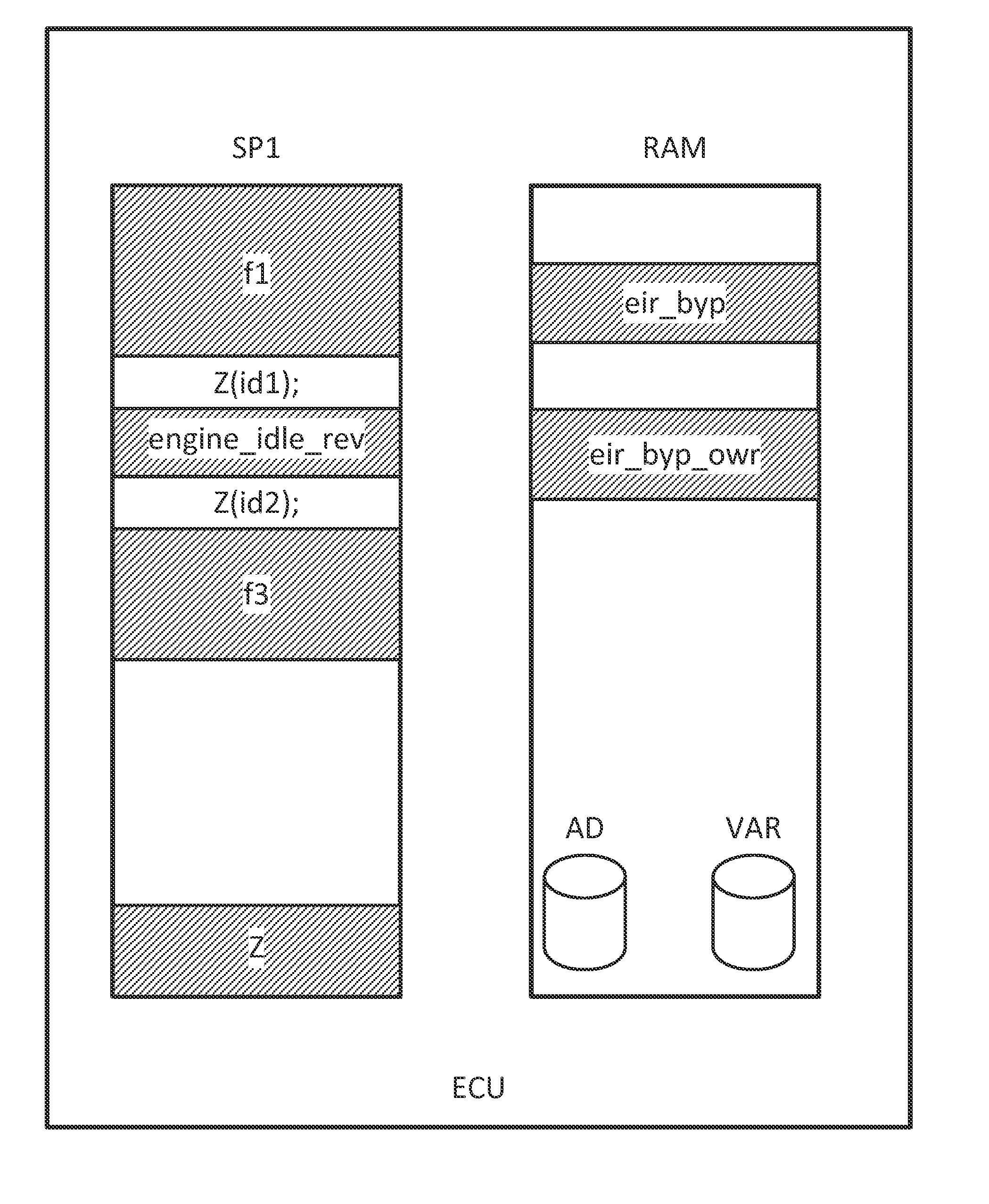
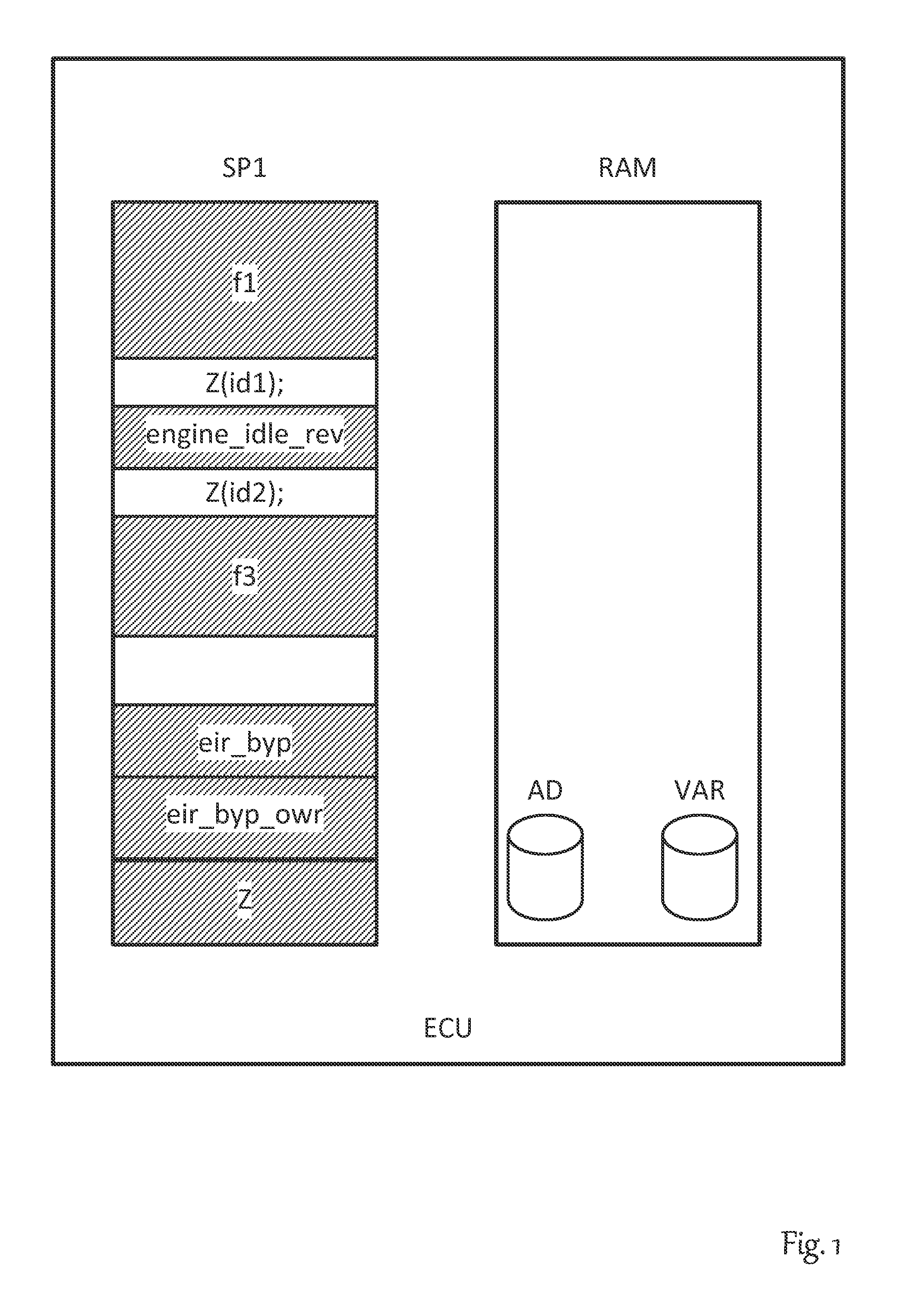
[0062]FIG. 1 illustrates the basic principle of service-based internal function bypassing. A development control unit ECU has a read-only memory SP1, as a rule a flash memory, and also has a working memory RAM. Located in the read-only memory SP1 is a program coded in machine language with multiple program routines, here comprising by way of example the routines f1, engine_idle_rev and f3. The number of routines is sharply reduced here for reasons of illustration. An actual control unit program typically has several hundred individual routines.

[0063]In one realistic example application, the control unit ECU is an engine control unit and the routine engine_idle_rev is a routine for controlling the idle speed. To reduce fuel consumption, it is useful to keep the idle speed of the engine as low as possible, or in other words, close to the speed that is just sufficient to maintain the operation of the engine.

[0064]However, this value is not a constant defined for every engine model, but...


PUM


Abstract

A method for changing a software in the memory of an electronic control unit. A bypass routine is stored in the working memory of the electronic control unit, and the address of the bypass function is stored in a table. A service function reads the address from the table and calls the bypass routine. The bypass routine is replaceable at the run time of the electronic control unit by erasing the table entry. The call of the service function is integrated into the program code of the electronic control unit by an overlay memory, a memory management unit, or with the aid of watch points.

Description

[0001]This nonprovisional application claims priority under 35 U.S.C. §119(a) to European Patent Application No. 13196209.4, which was filed in Europe on Dec. 9, 2013, and which is herein incorporated by reference.BACKGROUND OF THE INVENTION[0002]1. Field of the Invention[0003]The invention relates to a method for changing the software in the memory of an electronic control unit, wherein the memory includes at least one read-only memory with multiple original program routines stored therein that constitute at least a portion of the software and that are processed by at least one processor of the control unit, and that additionally has at least one working memory for storing volatile data, wherein a bypass routine is stored on the control unit that is processed in addition to or instead of at least one original program routine, which is accomplished in that, during the course of program steps being processed by the processor, the call to a service function is made at least prior to t...

Claims


Application Information

Patent Timeline
Patent Type & Authority Applications(United States)
IPC IPC(8): G06F9/445
CPCG06F8/67G06F8/65G06F8/66G06F8/656
Inventor HUFNAGEL, THORSTENDRESSLER, MARCKELLERS, BASTIAN
Owner DSPACE DIGITAL SIGNAL PROCESSING & CONTROL ENG
Why Eureka
Try Eureka