Integrated microinverter housing for a pv ac module

a micro-inverter and integrated technology, applied in the field of micro-inverters, can solve the problems of increasing the cost and reducing the service life of the power conditioning system

Active Publication Date: 2015-06-11
SPARQ SYST INC
View PDF7 Cites 6 Cited by
  • Summary
  • Abstract
  • Description
  • Claims
  • Application Information

AI Technical Summary

Problems solved by technology

These components contribute to the overall losses of the power conditioning system.
Also, these components increase the cost of the power conditioning systems.
Therefore, the main drawbacks of this approach are higher cost and longer installation time.
The arrangement in FIG. 1 is, unfortunately, also less than desirable.
The cables connecting the microinverter to the junction box are exposed to the elements and, as such, are vulnerable to the ravages of cold, heat, and wind.
As well, if repair work is to be done on the PV module or on any of the components of the PV system, these loose cables are susceptible to snagging by repair and maintenance personnel.
Also, the presence of both AC and DC connectors and the presence of the junction box itself not only can be confusing but may also complicate the installation of PV systems.

Method used


Image

  • Integrated microinverter housing for a pv ac module
  • Integrated microinverter housing for a pv ac module
  • Integrated microinverter housing for a pv ac module

Examples


Embodiment Construction

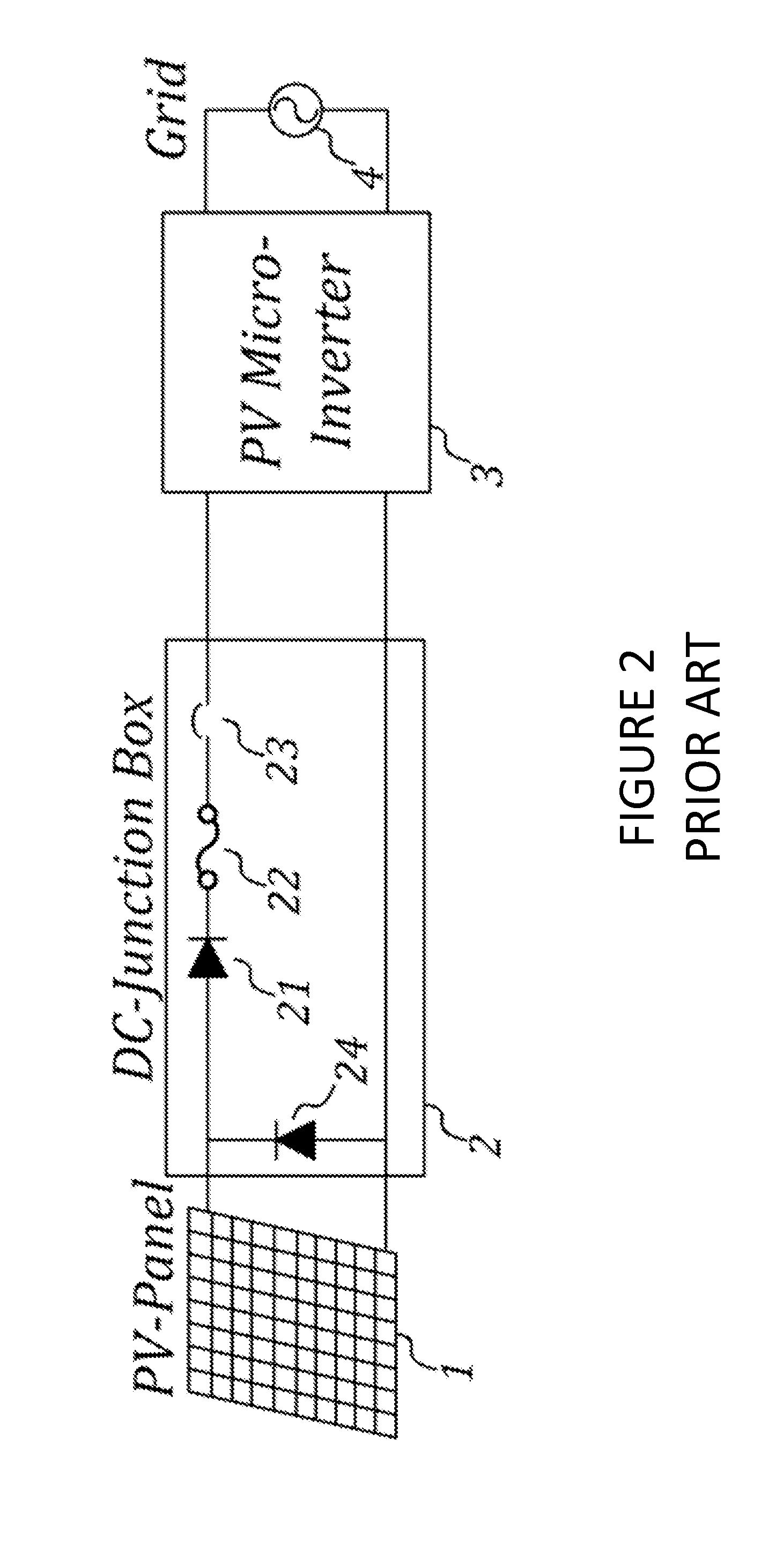
[0025]Referring to FIG. 3, a block diagram of a system incorporating one aspect of the invention is illustrated. In the system of FIG. 3, the DC junction box, DC cables and DC connectors are eliminated. The system has a PV panel coupled to an integrated AC module 5 which, in turn, feeds AC power to a power grid. A single micro-inverter unit 5 takes the DC input directly from the PV panel 1 and produces AC electricity to feed to the AC power grid 4.

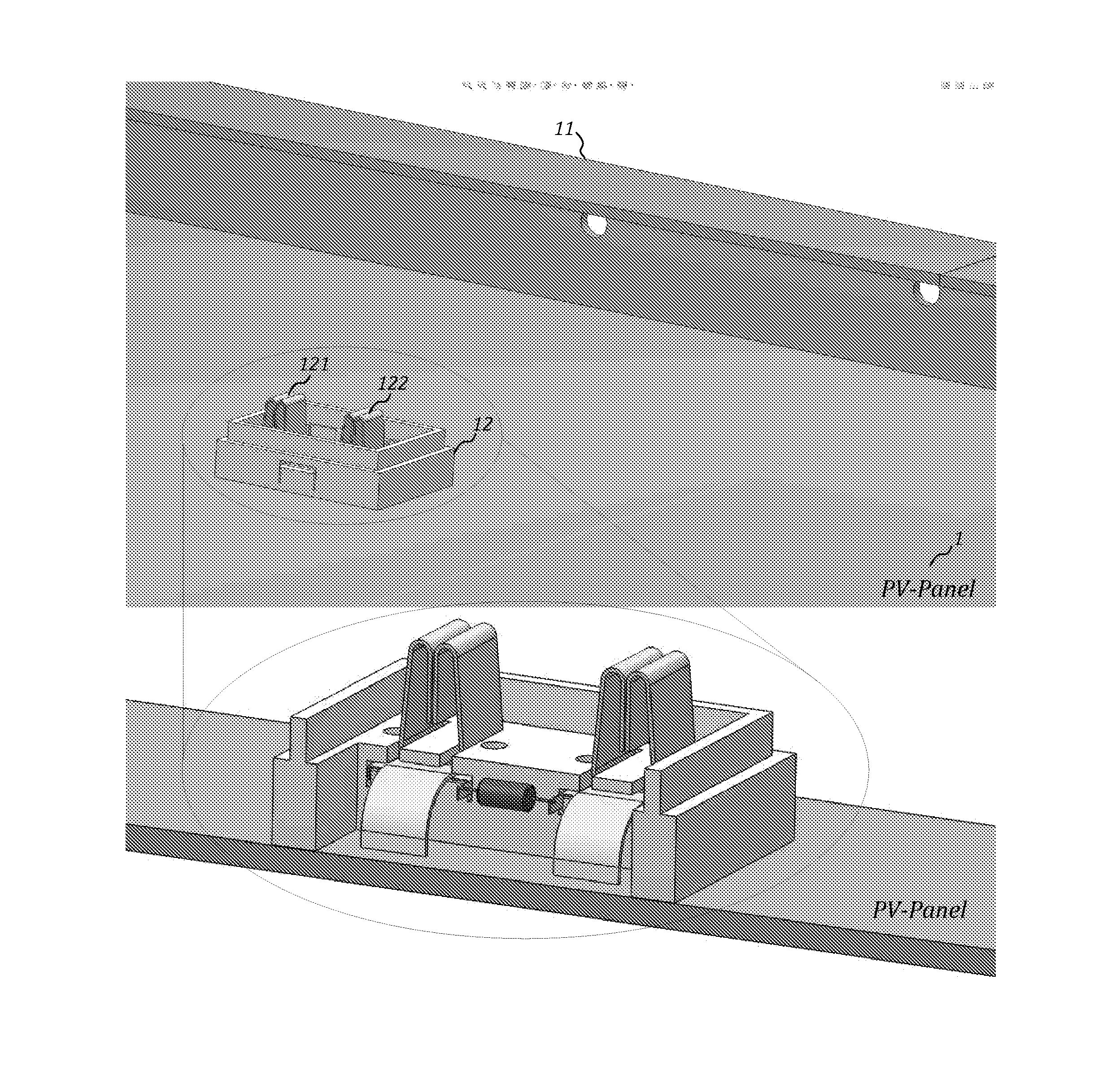
[0026]FIG. 4 illustrates a housing containing an integrated module 5 with the housing deployed on a PV panel 1. The integrated AC module 5, is directly connected to the DC wires which originate with the PV panel, 1. The housing containing the integrated AC module 5, has a top plate, 51, and a main compartment 52. A view of the housing with the top plate removed is provided in FIG. 5A. As can be seen from FIG. 5A, the main compartment 52 has a cavity 52A where the main inverter circuitry can be deployed or positioned. A void 52B is also pro...


PUM


Abstract

Systems and devices relating to an integrated housing for microinverters. The housing has a cavity for housing the circuitry of the microinverter. The housing is mountable on a back sheet of a PV module by way of the housing's top cover. An opening at the back of the housing accommodates DC contacts coming from the PV module while a void configured for an output port is also present in the housing. When mounted on the PV module, the housing is spaced apart from the module.

Description

RELATED APPLICATIONS[0001]This application is a non-provisional application which claims the benefit of U.S. Provisional Patent Application No. 6 / 912,950 filed on Dec. 6, 2013.TECHNICAL FIELD[0002]The present invention relates to microinverters. More specifically, the present invention relates to housings for microinverters that address the issue of untidy cabling and input and output ports.BACKGROUND OF THE INVENTION[0003]There is a growing number of photovoltaic (PV) applications where individual direct current / alternating current (DC / AC) inverters are required for each PV module to effectively harvest maximum solar energy and feed clean AC electricity into the power grid. FIG. 1 is a diagram that illustrates the prior art approach to achieving the requirements of such applications. In this prior art approach, a DC junction box is attached at the back-sheet of the PV module. The junction box accepts the DC voltage from the PV cells, provides the necessary protection, and brings ou...

Claims


Application Information

Patent Timeline
Patent Type & Authority Applications(United States)
IPC IPC(8): H05K7/14H01L31/024H01L31/02H05K7/20H01L31/05
CPCH05K7/1428H05K7/20509H01L31/024H01L31/02021H01L31/05H02S40/34H02S40/32H02S40/425H02J2300/24H02J3/381Y02E10/56Y02E10/50
Inventor ZHANG, HAIBODRESSEL, JANJAIN, PRAVEENPAHLEVANINEZHAD, MAJIDPAN, SHANGZHI
Owner SPARQ SYST INC
Why Eureka
Try Eureka