End cap for wiper assembly

Active Publication Date: 2015-06-18
TRICO PROD CORP
View PDF4 Cites 2 Cited by
  • Summary
  • Abstract
  • Description
  • Claims
  • Application Information

AI Technical Summary

Benefits of technology

The present invention is an end cap for a wiper assembly that prevents the splines (the part that connects the wiper to the support member) from moving sideways. The end cap has channels and tangs that fit together to keep the splines in a specific position, allowing the wiper to move smoothly and improving wipe quality performance. This invention can be used for any type of vehicle or transportation that has a surface wiper system.

Problems solved by technology

One disadvantage of the above wiper assemblies is that the splines may pinch the wiping element resulting in lower performance of the wiping assembly when the wiping element moves back and forth across the surface of the glass.
Another disadvantage is that the splines may move laterally once the end cap is attached to the splines.

Method used


Image

  • End cap for wiper assembly
  • End cap for wiper assembly
  • End cap for wiper assembly

Examples


Embodiment Construction

)

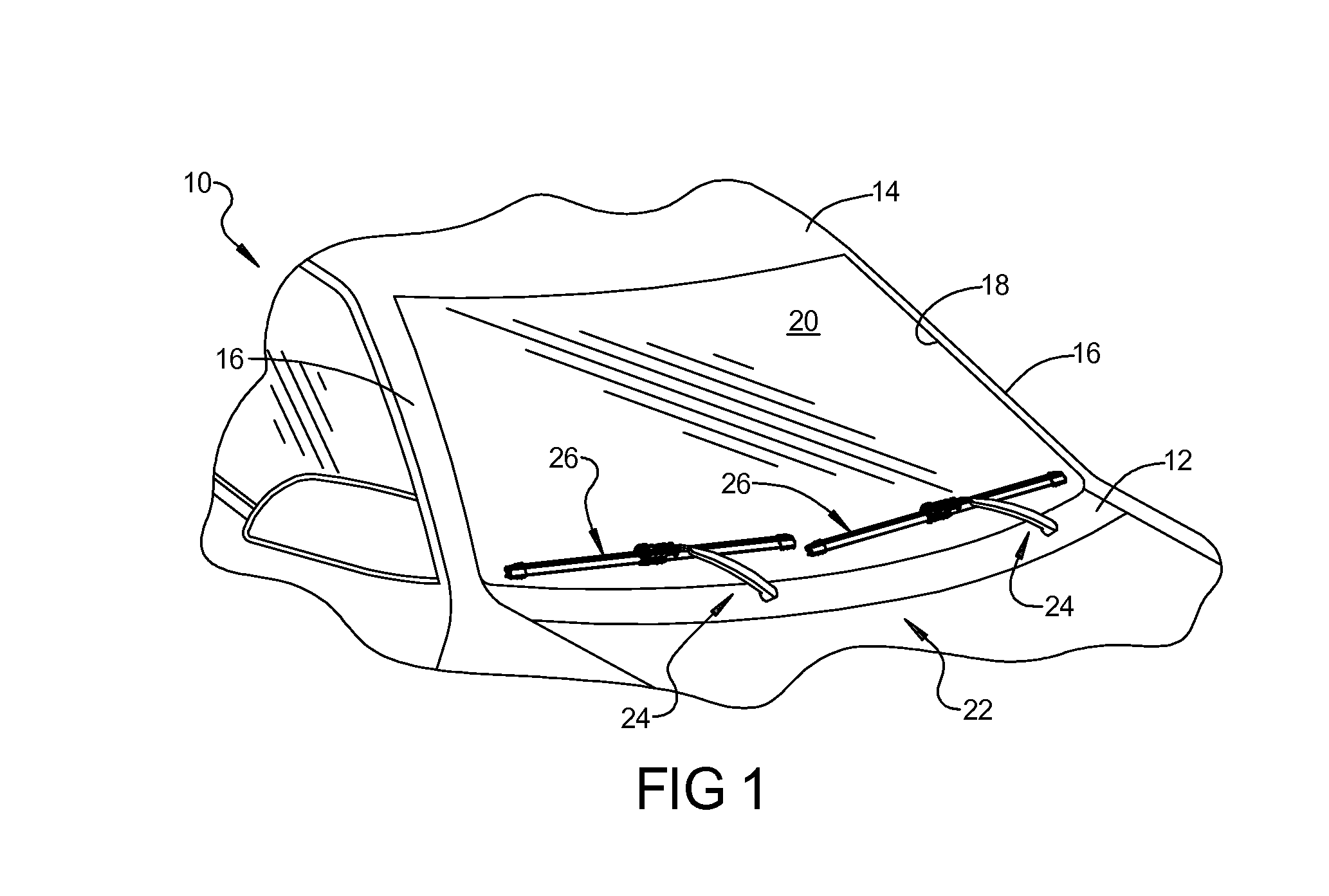
[0023]Referring now to the figures, where like numerals are used to designate like structure, a portion of a vehicle is schematically illustrated at 10 in FIG. 1. The vehicle 10 includes a cowl 12, a roof 14, and a pair of laterally spaced front or “A” pillars 16 extending between the roof 14 and the cowl 12. The A-pillars 16, roof 14, and cowl 12 cooperate to define a generally rectangular opening 18 in which is supported a curved or “swept back” glass windshield 20. As illustrated, the vehicle 10 is an automotive vehicle, but may be any type of vehicle such as heavy-duty trucks, trains, air planes, ships, large construction vehicles, or military vehicles or any other type of vehicle that contain surface wiper systems.

[0024]A wiper system is generally indicated at 22 in FIG. 1 and is employed to clean the windshield 20. The wiper system 22 includes a pair of wiper arms, generally indicated at 24, and a pair of wiper assemblies, according to one embodiment of the present invention ...


PUM


Abstract

An end cap for a wiper assembly includes a body adapted to be disposed over a portion of a plurality of splines of the wiper assembly. The body includes a separator adapted to cooperate with the splines of the wiper assembly to separate and retain the splines laterally from movement for a wiping element of the wiper assembly disposed between the splines.

Description

BACKGROUND OF THE INVENTION[0001]1. Field of the Invention[0002]The present invention relates generally to wiper assemblies for vehicles and, more specifically, to an end cap for a wiper assembly.[0003]2. Description of the Related Art[0004]Conventional wiper systems for vehicles known in the related art include some type of wiper assembly mounted to a wiper arm which, in turn, is mounted adjacent a surface to be wiped such as a windshield of the vehicle and pivotally driven to impart reciprocal motion to the wiper assembly across the windshield. The wiper assembly typically includes a rubber wiping element that contacts the windshield across the surface to be wiped. The wiper assembly often incorporates a support member in the form of one or more metal strips that act to reinforce the wiping element and facilitate wiping contact by the wiping element across what is typically a curved glass surface. In this context, the wiper arm delivers a downward force to the wiper assembly that ...

Claims


Application Information

Patent Timeline
IPC IPC(8): B60S1/38
CPCB60S1/3886B60S1/3896B60S1/381B60S1/3894
Inventor MOLL, KYLETHIELEN, C. JOSEPH
Owner TRICO PROD CORP
Why Eureka
Try Eureka