Tuned cavity rotating detonation combustion system

a combustion system and detonation wave technology, which is applied in the direction of mechanical equipment, machines/engines, lighting and heating apparatus, etc., can solve the problem of compromising the benefits of detonation wave pressure gain

Active Publication Date: 2015-06-18
GENERAL ELECTRIC CO
View PDF8 Cites 37 Cited by
  • Summary
  • Abstract
  • Description
  • Claims
  • Application Information

AI Technical Summary

Benefits of technology

[0004]In accordance with another example of the technology disclosed herein, a rotating detonation combustion system comprises a detonation chamber having an inner wall, an outer wall, an inlet and an outlet; a valve plate at the inlet of the annular chamber and comprising a plurality of openings spaced around the inlet; a plurality of tubes each having an open end in communication with a corresponding opening of the valve plate and a closed end forming a tuned cavity, and a first ...

Problems solved by technology

However, this compromises the benefits of...

Method used


Image

  • Tuned cavity rotating detonation combustion system
  • Tuned cavity rotating detonation combustion system
  • Tuned cavity rotating detonation combustion system

Examples


Embodiment Construction

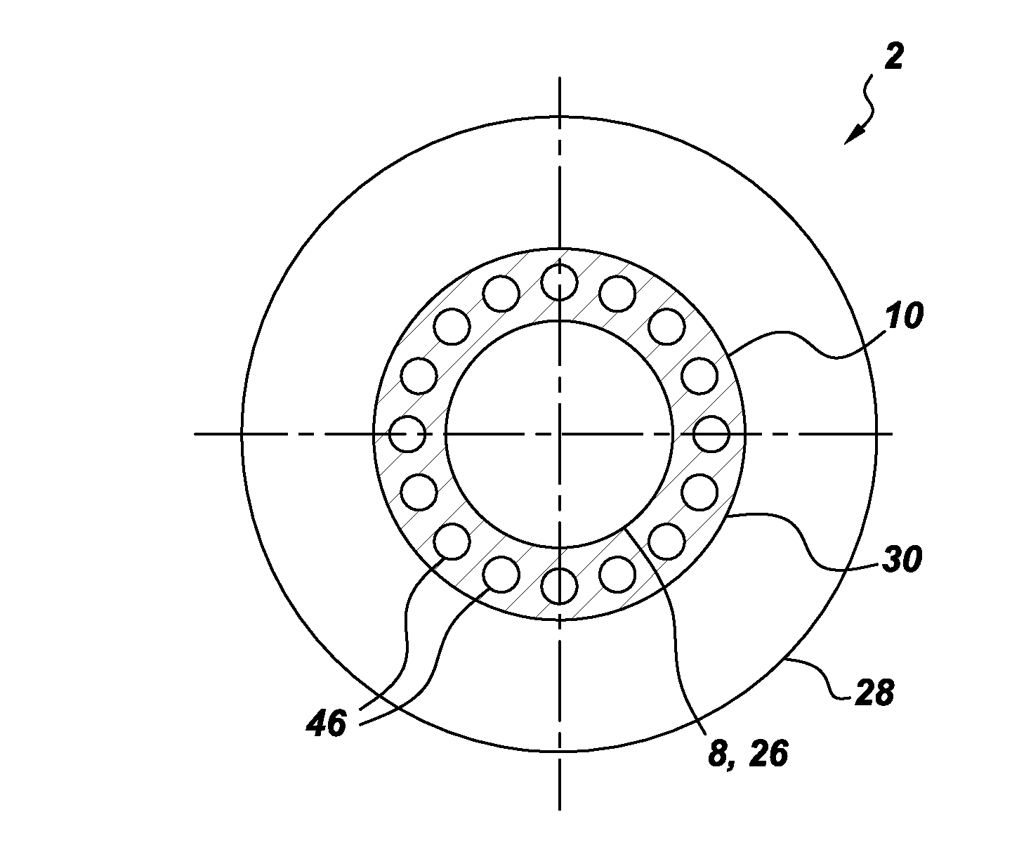
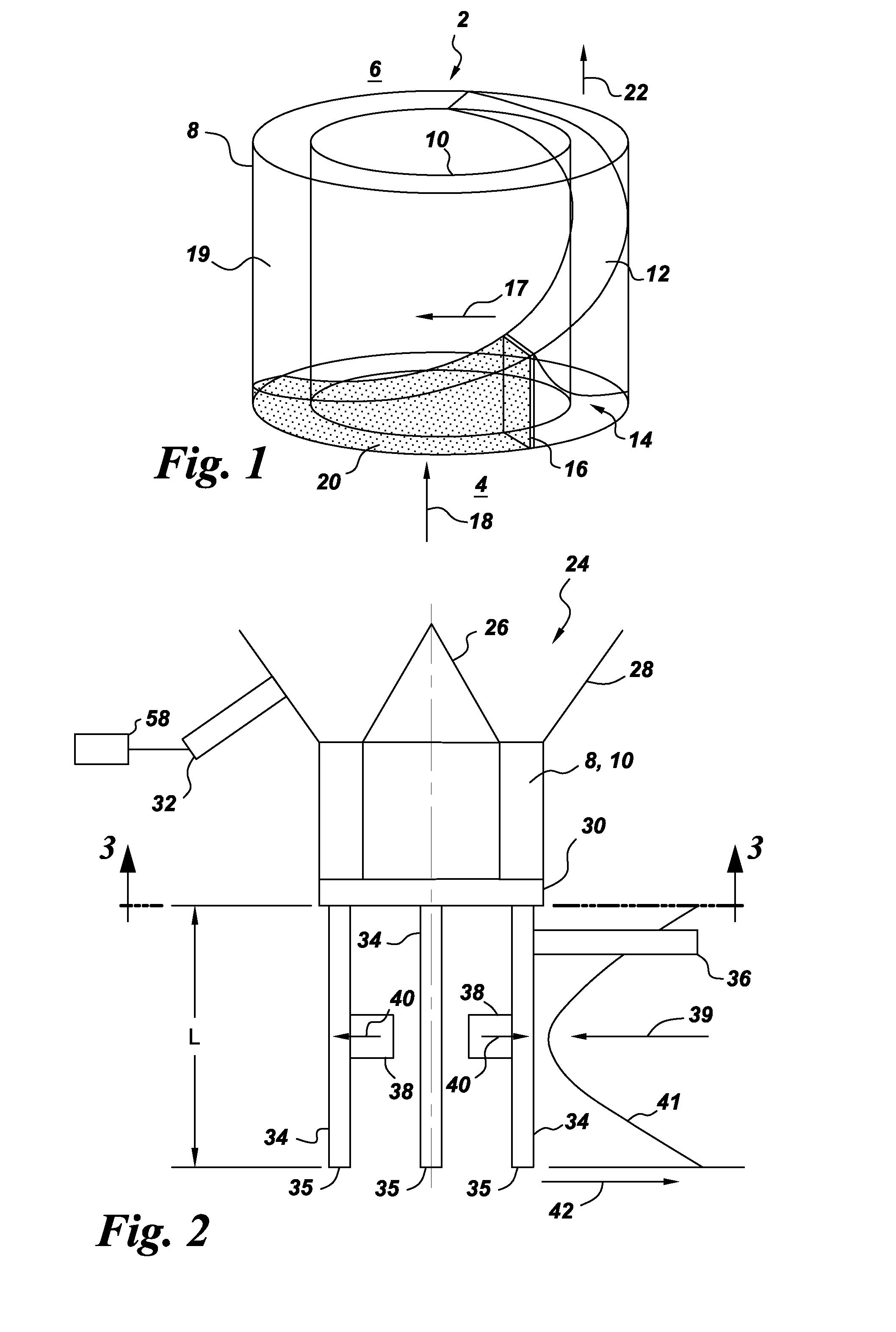
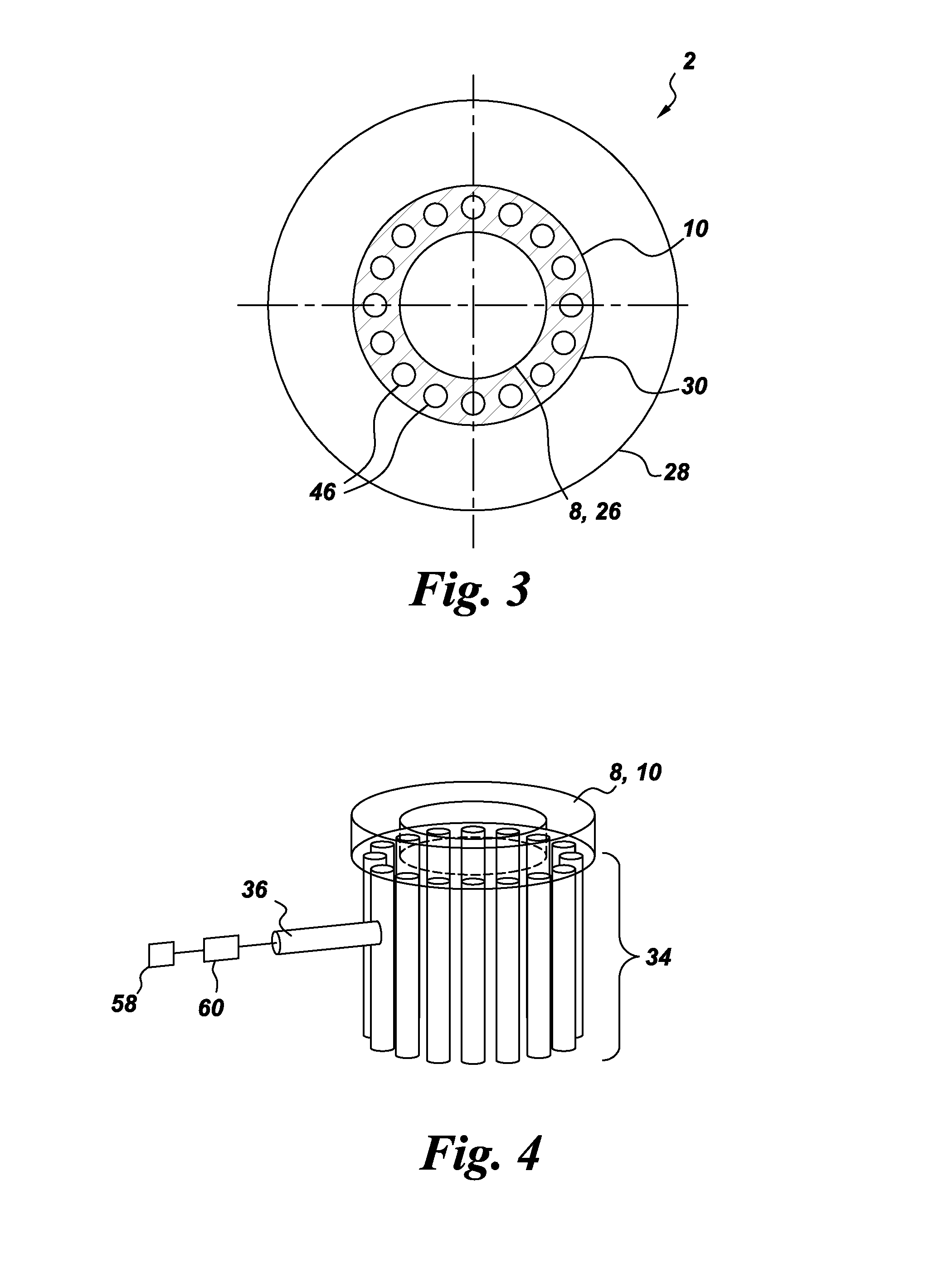
[0023]Referring to FIGS. 2-5, a rotating detonation combustion system 2 according to an example of the present technology may include a rotatable detonation annulus having an outer wall 8 and an inner wall 10. It should be appreciated that the walls 8, 10 of the annulus may form a cylindrical annulus as shown in FIG. 1, but that walls 8, 10 may also be curved, or may define a conical annulus. As shown in FIGS. 2 and 3, a stationary valve plate 30 with a plurality of holes 46 corresponding to a plurality of tubes 34 is positioned adjacent to the inlet end of the annulus 8, 10 and an exhaust nozzle 24 is provided to the exit end of the annulus 8, 10. The exhaust nozzle 24 may include an outer wall 28 and an inner wall 26 configured to direct the exhaust from the annulus 8, 10. An igniter 32 may be provided in the outer wall 28 to ignite the fuel / air mixture to provide combustion gases. Although one igniter 32 is shown in the drawing, it should be appreciated that more than one igniter...


PUM


Abstract

A tuned cavity rotating detonation combustion system includes a an annular chamber having an inlet and an outlet; a valve plate at the inlet of the annular chamber and comprising a plurality of openings spaced circumferentially around the inlet; a plurality of tubes each having an open end in communication with a corresponding opening of the valve plate and a closed end forming a tuned cavity, and a first opening between the open end and the closed end for injection of air; and a plurality of fuel injectors corresponding to the plurality of tubes, each fuel injector being configured to inject fuel into the tube between the first opening and the open end. Each of the tuned cavities has a length sized to resonate at a same frequency as a continuous detonation frequency of at least one detonation wave in the annular chamber. Alternately, or additionally, a plurality of flame arresters corresponding to the plurality of tubes are configured to arrest the at least one detonation wave generated in the detonation chamber from travelling into the tube.

Description

BACKGROUND[0001]The present technology relates generally to tuned cavity rotating detonation pressure gain combustion systems, and more particularly, to a system for liquid fuel injection into a tuned cavity rotating detonation combustion system.[0002]Rotating, or continuous, detonation pressure gain combustion systems are expected to have significant advantage over pulse detonation pressure gain combustors as the net non-uniformity of flow entering the turbine is expected to be lower by a factor of 2-10. One of the limitations of a rotating detonation combustor is inlet valving. The inlet valving has to work at kilohertz frequency range rather than the tens of hertz frequency range of the pulse detonation combustors. Mechanical valves that operate at such high frequencies are not practical.BRIEF DESCRIPTION[0003]In accordance with one example of the technology disclosed herein, a rotating detonation combustion system comprises an annular chamber having an inlet and an outlet; a val...

Claims


Application Information

Patent Timeline
IPC IPC(8): F02B53/04
CPCF02B53/04F23R7/00F02C5/02F23R3/14
Inventor JOSHI, NARENDRA DIGAMBERIDELCHIK, MICHAEL SOLOMON
Owner GENERAL ELECTRIC CO
Why Eureka
Try Eureka