Gas-filling apparatus and method for filling gas
- Summary
- Abstract
- Description
- Claims
- Application Information
AI Technical Summary
Benefits of technology
Problems solved by technology
Method used
Image
Examples
first embodiment
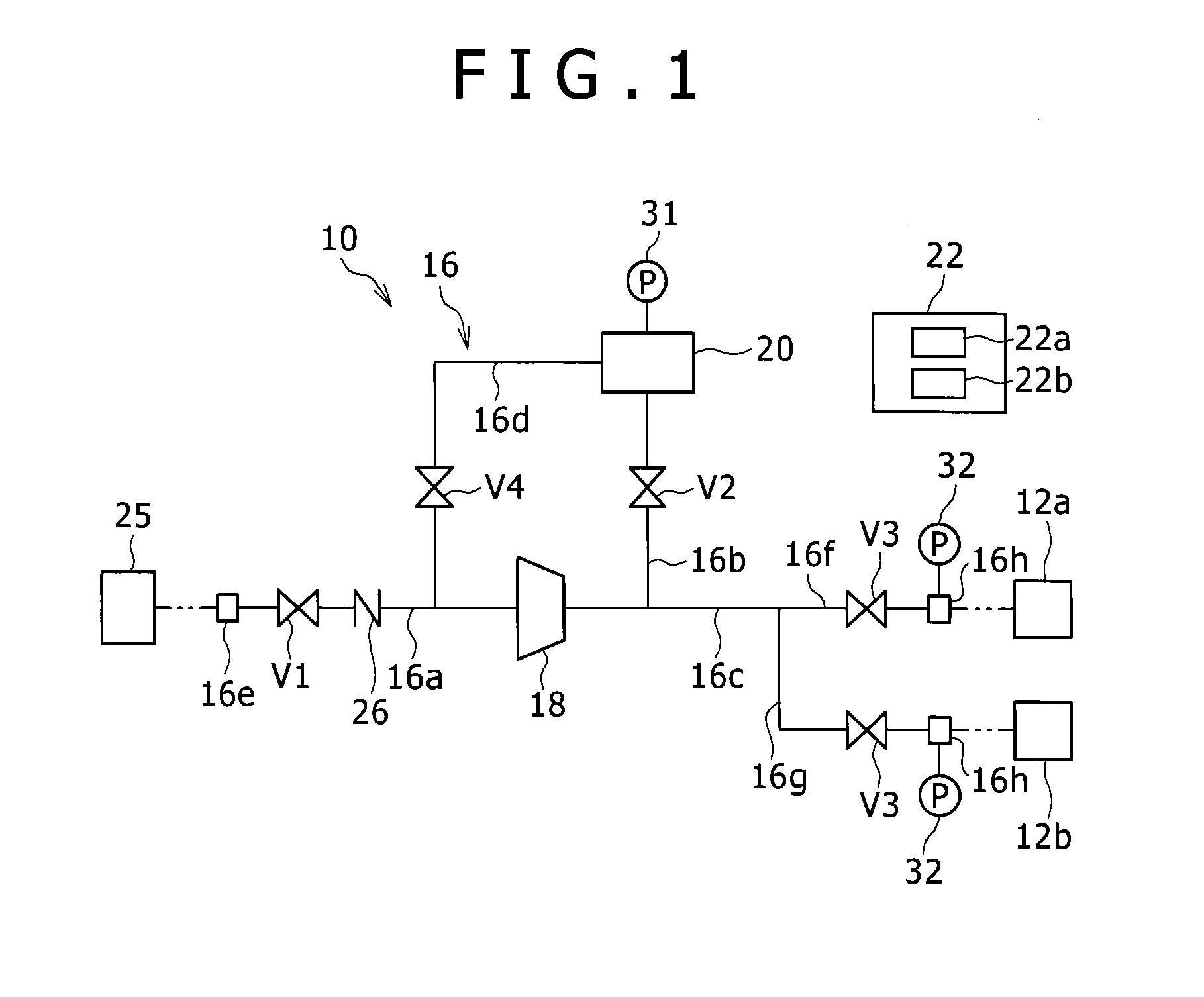
[0041]As illustrated in FIG. 1, a gas-filling apparatus 10 according to a first embodiment of the present invention serves to fill hydrogen gas (gas) into pressure accumulators 12a, 12b arranged at a hydrogen station, for example, serving as a hydrogen gas filling stand. The hydrogen gas having a preliminarily set predetermined pressure is stored in the pressure accumulators 12a, 12b. A dispenser not shown is connected to the pressure accumulators 12a, 12b and the hydrogen gas stored in the pressure accumulators 12a, 12b is supplied through the dispenser to a fuel-cell vehicle corresponding to a tank mounting unit.
[0042]The gas-filling apparatus 10 is provided with a gas flow passage 16 for distributing the hydrogen gas, a compressor 18 connected to the gas flow passage 16, a storage portion 20 connected to the gas flow passage 16, and a controller 22. The storage portion 20 is configured by a single container or plural containers.
[0043]The gas flow passage 16 includes a first flow ...
second embodiment
[0070]Next, a second embodiment of the present invention will be described. In addition, same reference numbers are assigned to components in the second embodiment, which are similar to those in the first embodiment, and those details will not be explained herein.
[0071]As illustrated in FIG. 3, the gas-filling apparatus 10 according to the second embodiment is provided with the gas flow passage 16. The gas flow passage 16 includes the first flow passage 16a, the second flow passage 16b, the third flow passage 16c, a sixth flow passage 16j, and a seventh flow passage 16k.
[0072]The inflow end 16e to which the gas supply source 25 is connectable is arranged at the upstream end of the first flow passage 16a. The downstream end of the first flow passage 16a is connected to the suction portion of the compressor 18. The check valve 26 and a flow regulating valve 27 are arranged in the first flow passage 16a. The flow regulating valve 27 is configured by an electric-operated valve, an open...
third embodiment
[0099]A third embodiment of the present invention is illustrated in FIG. 7. In the third embodiment, the storage portion 20 is configured to include a first tank portion 20a and a second tank portion 20b which stores gas with higher pressure than the first tank portion 20a. In the third embodiment, the hydrogen gas is filled in the pressure accumulators 12a, 12b only by the differential pressure filling operation from the second tank portion 20b. Same reference numbers are assigned to components in the third embodiment, which are similar to those in the first embodiment, and those details will not be explained herein.
[0100]The flow regulating valve 27 is arranged in the first flow passage 16a. The flow regulating valve 27 is configured by an electric-operated valve, an opening degree of which is regulatable.
[0101]The first tank portion 20a is connected to one end of the second flow passage 16b and is connected to one end of the fourth flow passage 16d. The second tank portion 20b is...
PUM
| Property | Measurement | Unit |
|---|---|---|
| Pressure | aaaaa | aaaaa |
Abstract
Description
Claims
Application Information
 - R&D
- Intellectual Property
- Life Sciences
- Materials
- Tech Scout
- Unparalleled Data Quality
- Higher Quality Content
- 60% Fewer Hallucinations
Browse by: Latest US Patents, China's latest patents, Technical Efficacy Thesaurus, Application Domain, Technology Topic, Popular Technical Reports.
© 2025 PatSnap. All rights reserved.Legal|Privacy policy|Modern Slavery Act Transparency Statement|Sitemap|About US| Contact US: help@patsnap.com


