Magnetic Refrigeration System With Improved Flow Efficiency

a technology of magnetic refrigeration and flow efficiency, applied in the direction of refrigeration machines, machines using electric/magnetic effects, lighting and heating apparatus, etc., can solve the problems of under-utilization of magnetocaloric beds and reduce efficiency, and achieve the effect of facilitating balancing and reducing efficiency

Active Publication Date: 2015-06-18
ASTRONAUTICS CORPORATION OF AMERICA
View PDF6 Cites 66 Cited by
  • Summary
  • Abstract
  • Description
  • Claims
  • Application Information

AI Technical Summary

Benefits of technology

[0011]The present inventor has determined that substantial inefficiencies can arise in conventional magnetic refrigeration systems as a result of variations in the length, configuration and construction of the inter-communicating conduits used to conduct fluid within the complex circuits of the device. These variations can significantly underutilize the magnetocaloric beds reducing efficiency. Accordingly, the present invention provides a magnetic refrigeration system in which the conduits between the valve system and the magnetocaloric beds are balanced with respect to flow either when multiple conduits are active or over successive intervals of conduit activation. A rotary design with concentric positioning of the valves facilitates this balancing which considers not only steady-state resistance to flow but also dynamic effects caused by variations in conduit volume and / or elasticity.

Problems solved by technology

These variations can significantly underutilize the magnetocaloric beds reducing efficiency.

Method used


Image

  • Magnetic Refrigeration System With Improved Flow Efficiency
  • Magnetic Refrigeration System With Improved Flow Efficiency
  • Magnetic Refrigeration System With Improved Flow Efficiency

Examples


first embodiment

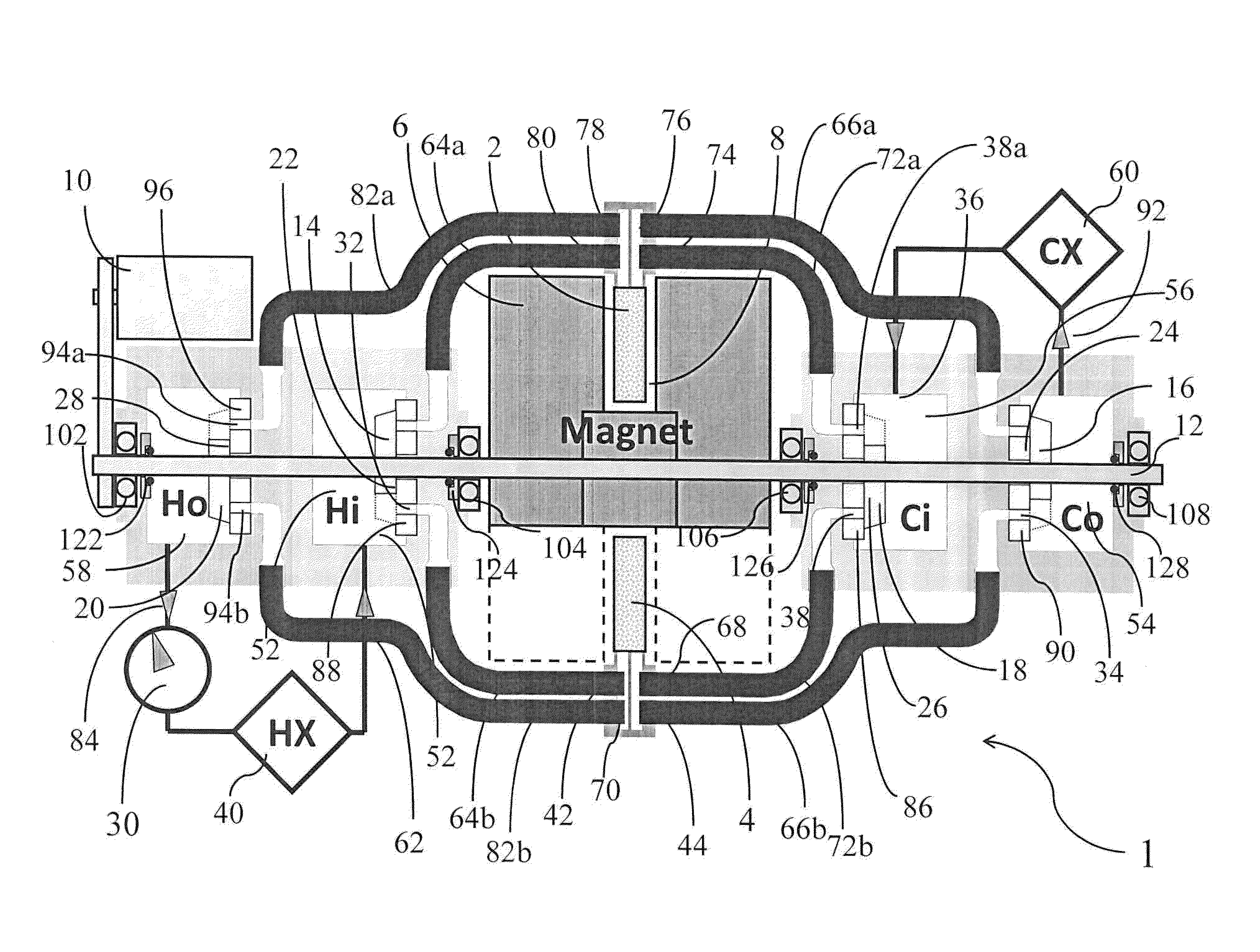
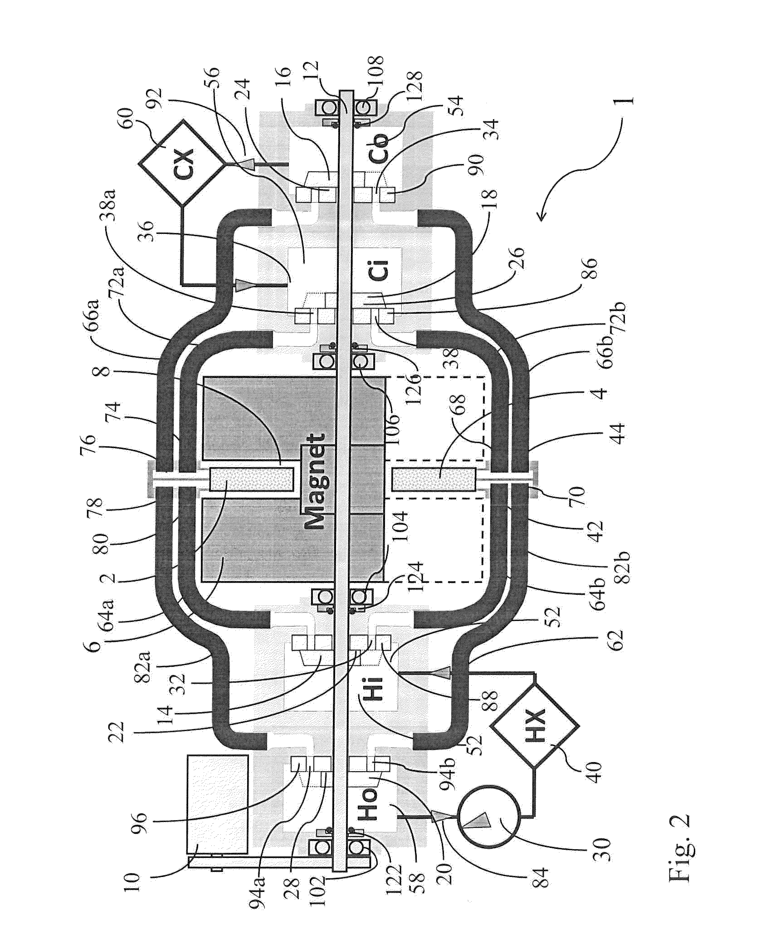
[0052]The invention comprises a “rotating magnet” magnetic refrigerator (RMMR) which uses rotary disk valves to control flow to and from the beds where these valves are located coaxially with the shaft rotating the magnet assembly. this invention is shown in FIG. 2. FIG. 2 shows a cross section of a two-bed system 1, where a first bed 2 (magnetized) is within the gap 8 of the magnet assembly 6 while a second bed 4 (demagnetized) is outside the gap 8 of the assembly. A motor 10 (which may be an electric motor) rotates the central shaft 12, which is mounted to bearings 102, 104, 106 and 108, and passes through rotary seals 122, 124, 126 and 128. This central shaft 12 also drives the rotors 14, 16, 18, 20 in each of the coaxial valves 22, 24, 26, 28. A pump 30 drives fluid flow through the system 1.

[0053]In the configuration shown in FIG. 2, the rotor 14 in the hot inlet (Hi) valve 22 uncovers the hole 32 connected to the hot inlet port 42 of the demagnetized (lower) bed 4. At the same...

sixth embodiment

[0072]Although this invention enables conduits of a similar flow function to be of equal length, conduits of dissimilar flow function, such as hot outlet and hot inlet, may be of different length. In the case where the flows in conduits of dissimilar flow function are not of the same magnitude, it may be advantageous to adopt a design where the conduits of functions that carry the highest flow rates are made the shortest. For example, in the case that was described in connection with FIG. 9, where four beds at a time undergo cold to hot flow while only two beds at a time undergo hot to cold flow, it could be advantageous to make the conduits carrying hot to cold flow shorter than the pipes carrying cold to hot flow. Note that the total hot to cold flow carried by all the beds is the same as the total cold to hot flow carried by all the beds, but because fewer beds carry cold to hot flow than carry hot to cold flow, the rate of flow in each conduit that carries cold to hot flow will ...


PUM


Abstract

A magnetic refrigeration system provides flow-balanced channels between fluid control valves and the magnetocaloric beds to eliminate inefficiencies caused by unequal utilization of the magnetic beds from flow variations.

Description

CROSS REFERENCE TO RELATED APPLICATION[0001]This application claims priority to U.S. provisional application Ser. No. 61 / 917,025, filed Dec. 17, 2013, the entire contents of which is incorporated herein by reference.STATEMENT REGARDING FEDERALLY SPONSORED RESEARCH OR DEVELOPMENTBACKGROUND OF THE INVENTION[0002]Magnetic refrigeration (MR) is an emerging cooling technology that is based on the magnetocaloric effect, a property exhibited by certain materials which heat up when placed in a magnetic field and cool down when the field is removed. Magnetic refrigeration offers a number of distinct advantages over vapor compression, which is currently the most widely used method for cooling. First, MR uses no hydrofluorocarbons (HFCs), chlorofluorocarbons (CFCs), nor any other gaseous materials; the refrigerant in the MR system is in the form of a porous solid. The absence of any gases greatly reduces the potential for leaks, a common problem in vapor compression systems. As a result, MR sy...

Claims


Application Information

Patent Timeline
Patent Type & Authority Applications(United States)
IPC IPC(8): F25B21/00
CPCF25B21/00F25B2321/002Y02B30/00F25B41/40F25B41/20
Inventor LEONARD, JOHN PAULAURINGER, JON JAYBOEDER, ANDRE MICHAELCHELL, JEREMY JONATHANZIMM, CARL BRUNO
Owner ASTRONAUTICS CORPORATION OF AMERICA
Why Eureka
Try Eureka