
Automatic compensation for the effect of grain properties on mass flow sensor calibration

a technology of mass flow rate and calibration characteristic, applied in the direction of volume flow testing/calibration, liquid/fluent solid measurement, instruments, etc., can solve the problems of inability to have highly accurate pre-determined calibration curves, inability to accurately calculate calibration characteristic, and inability to consider the effect of grain moisture or other grain parameters on calibration characteristi

Active Publication Date: 2015-06-18
LEADER TECH
View PDF6 Cites 36 Cited by
  • Summary
  • Abstract
  • Description
  • Claims
  • Application Information

AI Technical Summary

Benefits of technology

This patent describes a yield monitor system that detects how different factors affect the calibration of a sensor that measures the mass of grain on a combine. These factors can include moisture content, density, and other characteristics of the grain. The system uses calibration curves to determine how the sensor's calibration changes as a function of these factors. This helps to improve the accuracy of the grain mass flow sensor and ensure consistent measurements across different grain loads. The system also allows for the determination of calibration curve variation coefficients, which provide a better understanding of how the sensor's calibration fluctuates in response to changes in the grain's parameters. Overall, the system provides a more reliable and accurate tool for measuring the mass of grain on a combine.

Problems solved by technology

However, there are several problems with the prior art.
These problems make it impractical to have highly accurate pre-determined calibration curves, because it is not practical to determine calibration curves for all possible dimensional variations that occur in the components of a combine clean grain elevator.
This method does a good job of determining the calibration characteristics of the mass flow sensor at different grain flow rates, but does not consider the effect of grain moisture or other grain parameters on the calibration characteristic.
Calibration characteristics determined with loads having significantly different moistures or other grain parameters are not accurate for all moistures or grain parameters.

Method used


Image

  • Automatic compensation for the effect of grain properties on mass flow sensor calibration
  • Automatic compensation for the effect of grain properties on mass flow sensor calibration
  • Automatic compensation for the effect of grain properties on mass flow sensor calibration

Examples


Embodiment Construction

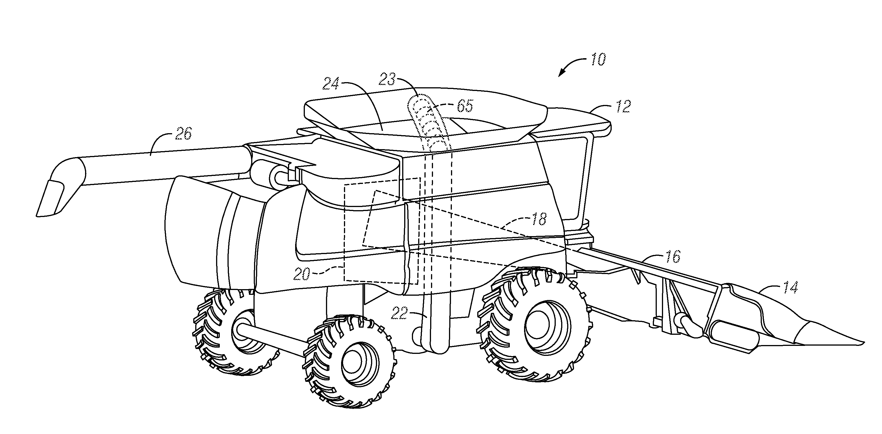
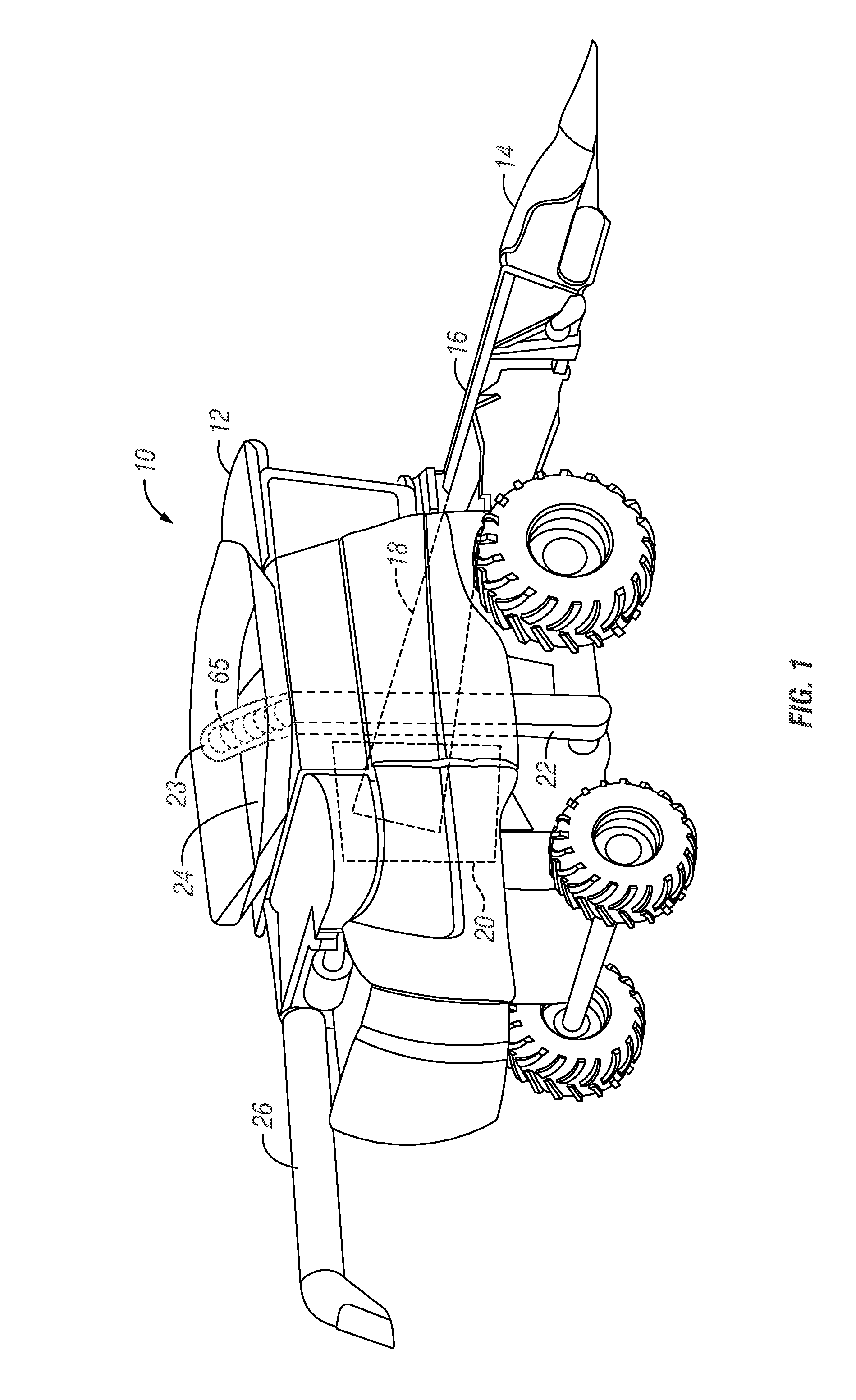
[0026]The present invention relates to yield monitoring and to calibration of a mass flow sensor in a yield monitoring system. FIG. 1 is a perspective view of one example of a harvesting machine or harvester in the form of a combine harvester or combine 10 which is equipped with a yield monitoring system. The combine harvester 10 includes a self-propelled vehicle 12 with an attached harvesting head 14 which is supported on a feeder house 16 at the front of the vehicle 12. A threshing system 18 is disposed within the combine harvester 10. The threshing system threshes crop material and conveys the threshed crop material to a cleaning and separating system 20. During a cleaning and separating process, grain falls to the bottom of the combine harvester and is then conveyed upward by a grain elevator 22 and through an auger 65 within an auger housing 23 to a grain tank 24. Grain may be stored in the grain tank 24 and later unloaded through an unloading conveyor or auger 26.

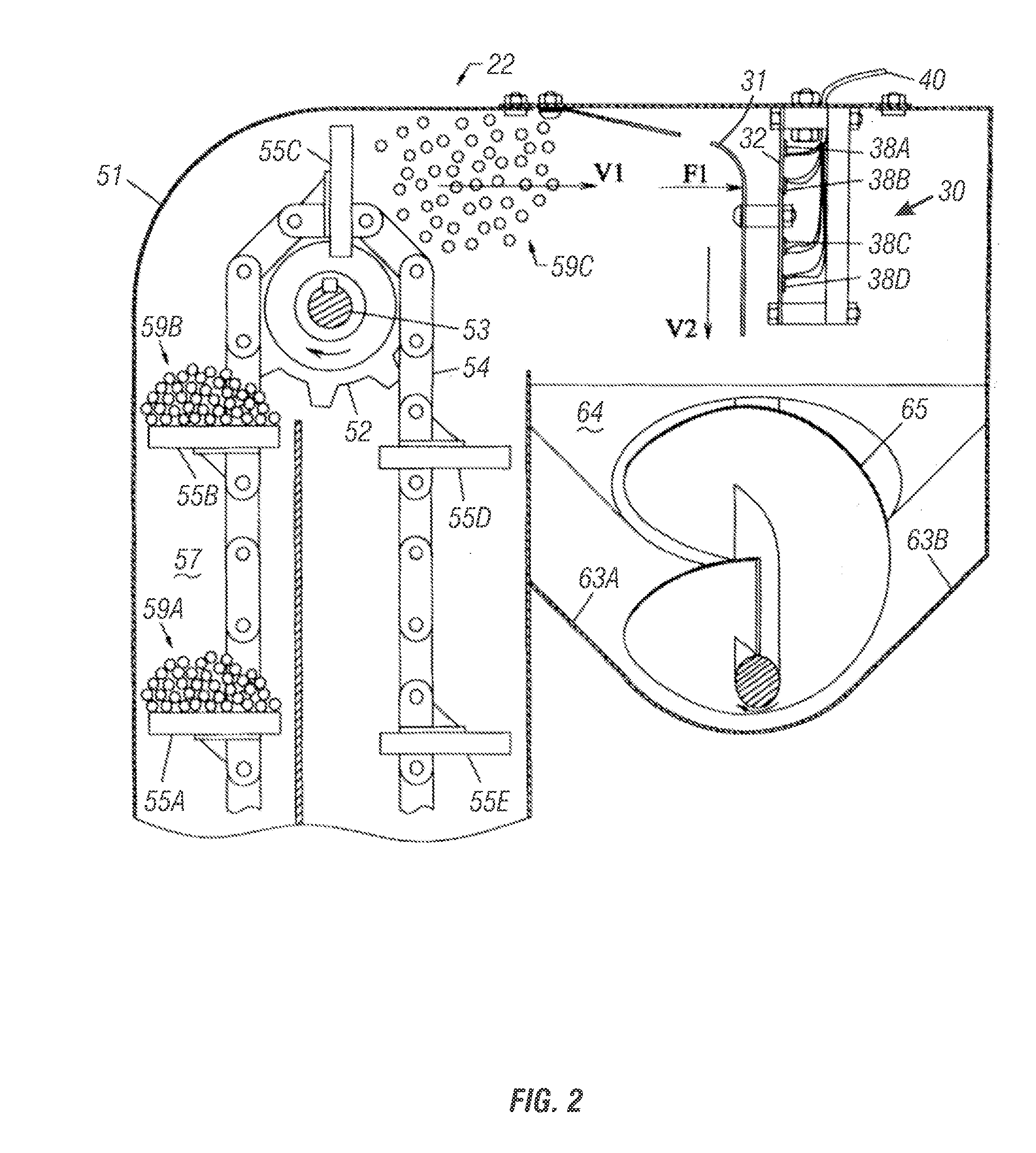
[0027]FIG. 2 ...


PUM


Abstract

A yield monitor system is configured to determine how the calibration characteristics of a grain mass flow sensor on an individual combine are affected by grain moisture content and / or other grain parameters which can be measured instantaneously or periodically by the yield monitor system or its operator, or which can be observed by the operator, or which can be determined from other reference information, such as maps of where different grain varieties or hybrids were planted. Other systems, methods, and apparatuses are also provided.

Description

PRIORITY STATEMENT This application claims priority under 35 U.S.C. §119 to provisional application U.S. Ser. No. 61 / 915,933 filed Dec. 13, 2013, hereby incorporated by reference in its entirety.FIELD OF THE INVENTION[0001]The present invention relates to methods, systems, and apparatus for calibrating a mass flow rate measuring system which is used to continuously measure grain mass flow rate in a harvester as grain is harvested.BACKGROUND OF THE INVENTION[0002]Grain mass flow sensors have become widely used on grain combines to measure and record instantaneous crop yield values, and to compute load, field and farm totals, as grain is harvested. An example of such a system is shown in U.S. Pat. No. 5,343,761, herein incorporated by reference in its entirety.[0003]Although the accuracy of such systems has been good enough allow combine yield monitors to become widely used, farmers and their advisers who analyze their yield data request better accuracy and less effort required to cal...

Claims


Application Information

Patent Timeline
IPC IPC(8): G01F1/20A01C7/10G01F1/80
CPCG01F1/206A01C7/105G01F1/80A01D41/1272G01F1/30A01D41/1277G01F25/10
Inventor MYERS, AL
Owner LEADER TECH
Learn More