RF shielding conduit in an MRI closure assembly

a shielding conduit and mri technology, applied in the field of magnetic resonance imaging systems, can solve the problems of affecting other devices in the vicinity of the mri process, affecting the operation affecting the operation of other scanning devices, etc., and causing the impedement of the mri process, and the cost of solutions tends to be high

Active Publication Date: 2015-06-18
ASPECT IMAGING
View PDF3 Cites 36 Cited by
  • Summary
  • Abstract
  • Description
  • Claims
  • Application Information

AI Technical Summary

Benefits of technology

[0009]The present invention provides, in a magnetic resonance imaging device (MRD) comprising (a) a main longitudinal axis with a distal and proximal ends; (b) an open bore extended along the axis and terminated by an aperture located in the proximal end; and (c) a closure assembly which is shaped to fit the aperture; an RF shielding conduit (RFSC), having apertures shaped to permit passage of medical equipment tubing from the external environment of the MRD to inner space of the bore, affixed to the closure assembly, wherein the conduit is characterized by a length (l) and width (w), l:w ratio is greater than a predefined value n, thereby providing RF shielding.

Problems solved by technology

Electromagnetic interference (EMI) that is generated in the process of MRI negatively affects other devices in its vicinity such as medical electrical devices, computers, data transfer components, other scanning devices, etc.
In addition EMI generated at an external source such as electric lines, television and radio signals, elevators, etc., can impede MRI operation and results.
This solution tends to be costly and requires adjusting and handling.
Disconnecting medical equipment for the purpose of imaging a patient takes time and may cause patient stress, or induce medical complications.
This hazardous phenomenon is known as the projectile, or missile, effect, which can potentially result in serious or fatal injuries to individuals in the scanner room.
Even objects, as small as a stapler pin, may be a potential risk.
Numerous severe accidents were recorded at MRI facilities because of pulled iron-containing objects.

Method used


Image

  • RF shielding conduit in an MRI closure assembly
  • RF shielding conduit in an MRI closure assembly
  • RF shielding conduit in an MRI closure assembly

Examples


Embodiment Construction

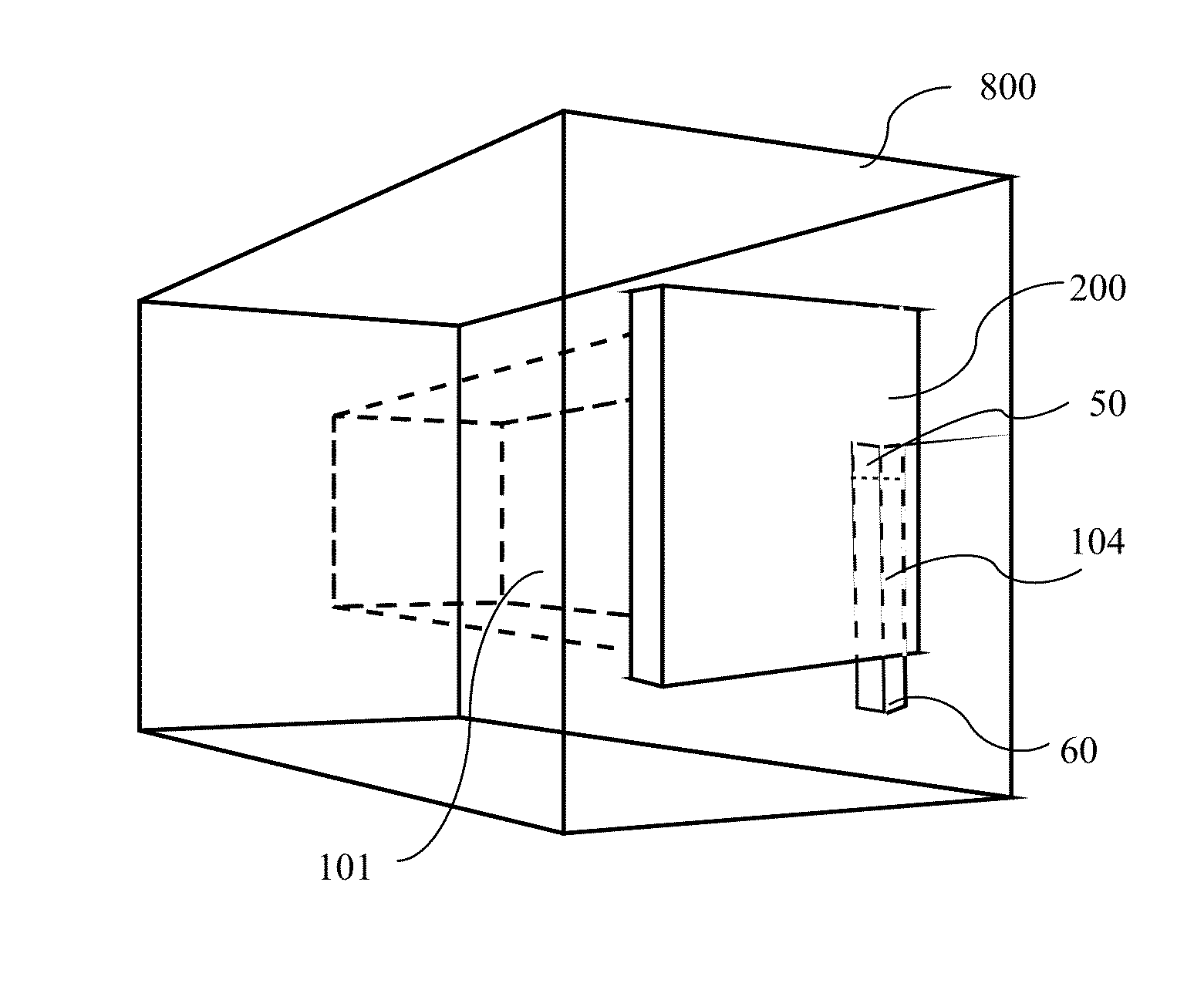
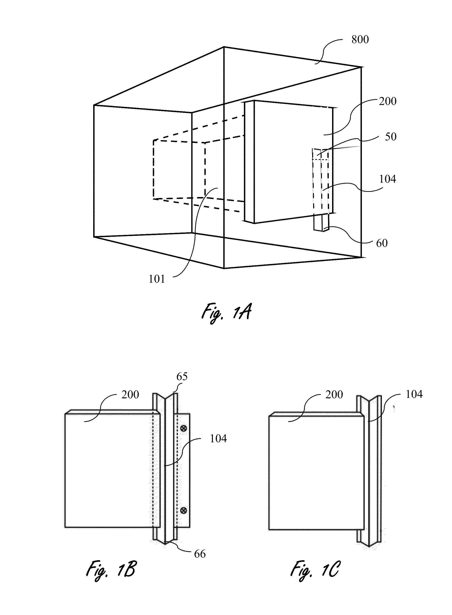
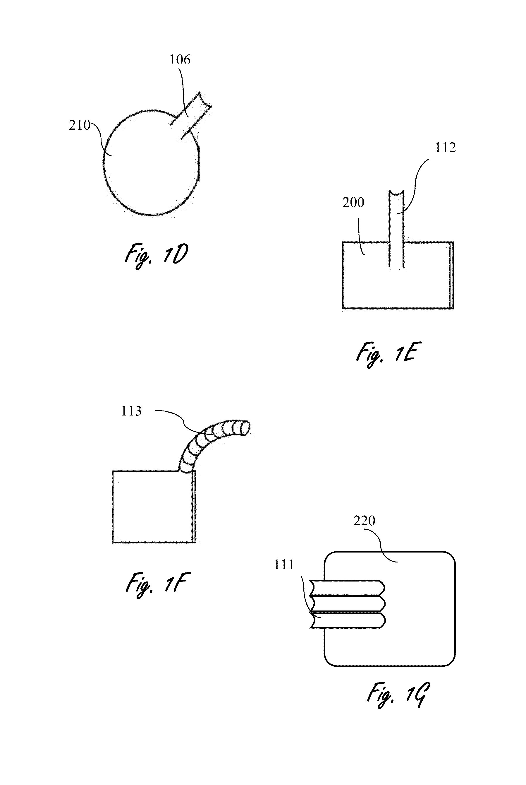
[0140]In the following detailed description of the preferred embodiments, reference is made to the accompanying drawings that form a part hereof, and in which are shown by way of illustration specific embodiments in which the invention may be practiced. It is understood that other embodiments may be utilized and structural changes may be made without departing from the scope of the present invention. The present invention may be practiced according to the claims without some or all of these specific details. For the purpose of clarity, technical material that is known in the technical fields related to the invention has not been described in detail so that the present invention is not unnecessarily obscured. The present invention provides a closure assembly for an MRI bore with means to facilitate the passage of medical equipment.

[0141]The essence of the present invention is to provide a RF shielding conduit, affixed to an MRD closure assembly that allows covering of an MRD bore ape...


PUM


Abstract

The present invention provides, in a magnetic resonance imaging device (MRD) comprising (a) a main longitudinal axis with a distal and proximal ends; (b) an open bore extended along the axis and terminated by an aperture located in the proximal end; and (c) a closure assembly which is shaped to fit the aperture; an RF shielding conduit (RFSC), having apertures shaped to permit passage of medical equipment tubing from the external environment of the MRD to inner space of the bore, affixed to the closure assembly, wherein the conduit is characterized by a length (l) and width (w), l:w ratio is greater than a predefined value n, thereby providing RF shielding.

Description

FIELD OF THE INVENTION[0001]The present invention generally relates to the field of magnetic resonance imaging systems (MRI), and more particularly, to an RF shielding conduit in an MRI closure assembly, for covering the aperture of an MRI bore, comprising passage for medical equipment that maintains RF shielding during its operation and methods thereof.BACKGROUND OF THE INVENTION[0002]MRI technology utilizes magnetism and radio frequency for imaging of patients for medical diagnosis and research. Electromagnetic interference (EMI) that is generated in the process of MRI negatively affects other devices in its vicinity such as medical electrical devices, computers, data transfer components, other scanning devices, etc. In addition EMI generated at an external source such as electric lines, television and radio signals, elevators, etc., can impede MRI operation and results.[0003]Facilities providing MRI services build specially designed rooms that allow MRI procedures to be shielded ...

Claims


Application Information

Patent Timeline
Patent Type & Authority Applications(United States)
IPC IPC(8): G01R33/422G01R33/48
CPCG01R33/48G01R33/422A61B5/055A61B2562/182G01R33/28H05K9/00G01R33/0052G01R33/42
Inventor RAPOPORT, URI
Owner ASPECT IMAGING
Why Eureka
Try Eureka