
Imaging lens and imaging apparatus

a technology of imaging apparatus and lens, applied in the field of imaging lens, can solve the problem that the imaging lens is usable in a limited environment, and achieve the effect of excellent performance and high image quality

Active Publication Date: 2015-06-18
TIANJIN OFILM OPTO ELECTRONICS CO LTD
View PDF1 Cites 21 Cited by
  • Summary
  • Abstract
  • Description
  • Claims
  • Application Information

AI Technical Summary

Benefits of technology

The present invention provides an imaging lens that has excellent performance at both normal temperature and high temperature, with a small change in focus position when temperature changes. The lens is made up of multiple lenses with specific refractive powers and a specific order in which they are arranged. Additionally, at least one of the lenses satisfies a specific conditional expression. The imaging lens and apparatus using it can provide high quality video images even in environments where there is large temperature change.

Problems solved by technology

Therefore, the imaging lens is usable in limited environment, compared with an imaging lens consisting of only material, such as glass, a change in the properties of which by a change in temperature is small.

Method used


Image

  • Imaging lens and imaging apparatus
  • Imaging lens and imaging apparatus
  • Imaging lens and imaging apparatus

Examples


Embodiment Construction

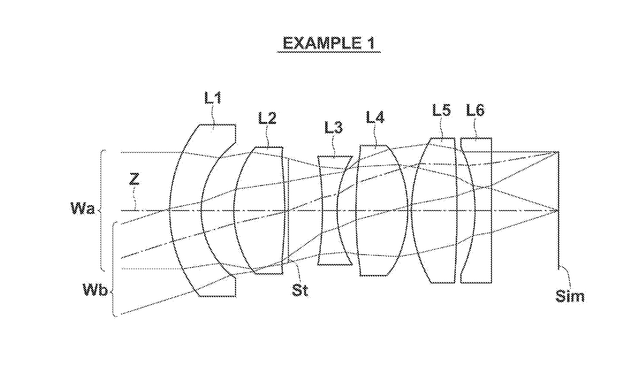
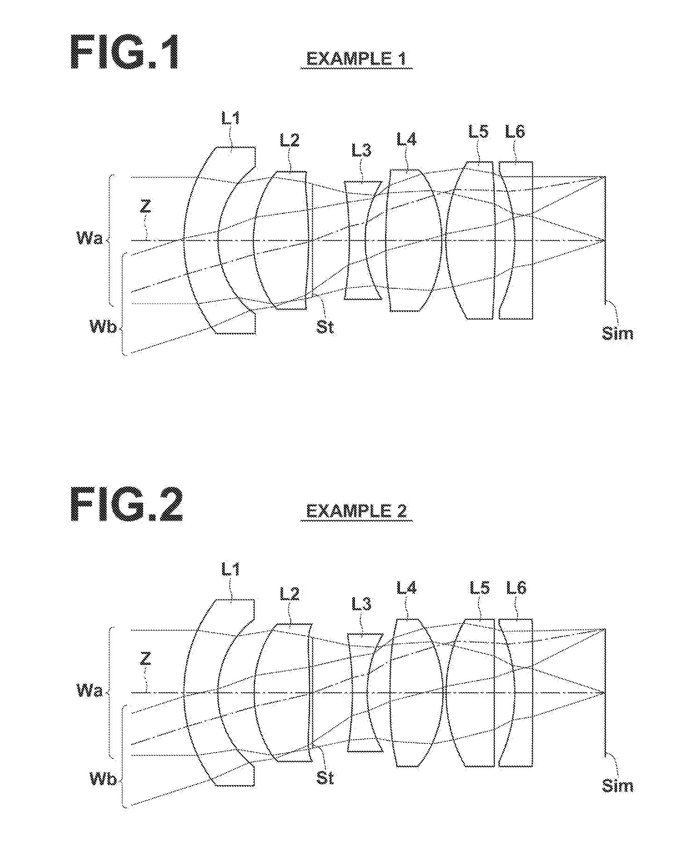
):

[0034]FIG. 2 is a cross section illustrating the lens structure of an imaging lens in Example 2 of the present invention:

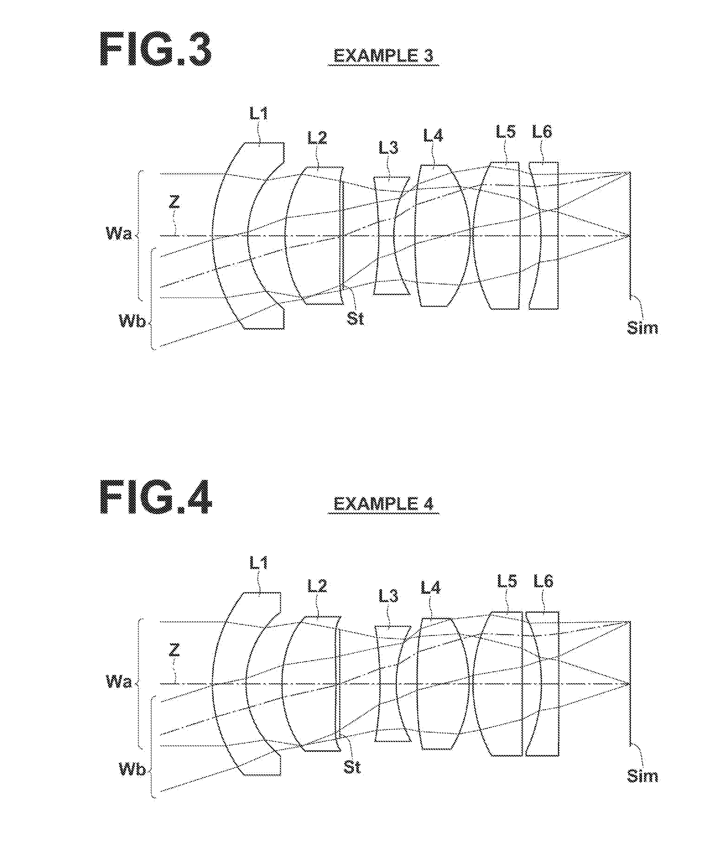
[0035]FIG. 3 is a cross section illustrating the lens structure of an imaging lens in Example 3 of the present invention;

[0036]FIG. 4 is a cross section illustrating the lens structure of an imaging lens in Example 4 of the present invention;

[0037]FIG. 5 is a cross section illustrating the lens structure of an imaging lens in Example 5 of the present invention;

[0038]FIG. 6 is a cross section illustrating the lens structure of an imaging lens in Example 6 of the present invention:

[0039]FIG. 7 is a cross section illustrating the lens structure of an imaging lens in Example 7 of the present invention;

[0040]FIG. 8 is a cross section illustrating the lens structure of an imaging lens in Example 8 of the present invention;

[0041]FIG. 9 is a cross section illustrating the lens structure of an imaging lens in Example 9 of the present invention;

[0042]FIG. 10 is a cross se...


PUM


Abstract

An imaging lens substantially consists of negative first lens, positive second lens, negative third lens, positive fourth lens, positive fifth lens, and negative sixth lens in this order from an object side. At least one of second lens through sixth lens satisfies the following conditional expression (1), and the imaging lens, as a whole, satisfies the following conditional expression (2):(1 / τi)×(f / fi)<0  (1); andΣ(1 / τi)×(f / fi)<0 (i=1 through 6)  (2).

Description

CROSS-REFERENCE TO RELATED APPLICATIONS[0001]The present application claims priority under 35 U.S.C. §119 to Japanese Patent Application No. 2013-260089, filed on Dec. 17, 2013. The above application is hereby expressly incorporated by reference, in its entirety, into the present application.BACKGROUND OF THE INVENTION[0002]1. Field of the Invention[0003]The present invention relates to an imaging lens especially appropriate for an on-vehicle camera, and an imaging apparatus including the imaging lens.[0004]2. Description of the Related Art[0005]As a compact imaging lens that has a long backfocus and is especially appropriate for an on-vehicle camera, an imaging lens consisting of a meniscus first lens having negative refractive power with its convex surface facing an object side, a second lens having positive refractive power, an aperture stop, a third lens having negative refractive power, a fourth lens having positive refractive power, a fifth lens having positive refractive powe...

Claims


Application Information

Patent Timeline
IPC IPC(8): G02B13/04G02B13/00G02B1/00G02B9/62
CPCG02B13/04G02B1/00G02B13/001G02B9/62G02B13/0045
Inventor KITAHARA, YU
Owner TIANJIN OFILM OPTO ELECTRONICS CO LTD
Learn More