Apparatus for detecting boundary line of vehicle lane and method thereof

Active Publication Date: 2015-06-18
DENSO CORP +1
View PDF2 Cites 19 Cited by
  • Summary
  • Abstract
  • Description
  • Claims
  • Application Information

AI Technical Summary

Benefits of technology

[0009]Therefore, it is desired that an apparatus and a method for detecting a boundary line of a vehicle lane be provided, the apparatus an

Problems solved by technology

The vehicle-lane boundary line cannot be appropriately detected.
An erroneous detection that the lane marker is correct may be made.
On a

Method used


Image

  • Apparatus for detecting boundary line of vehicle lane and method thereof
  • Apparatus for detecting boundary line of vehicle lane and method thereof
  • Apparatus for detecting boundary line of vehicle lane and method thereof

Examples


first example

[0033]First, a vehicle-lane boundary line detection apparatus of a first example will be described with reference to FIG. 1 to FIG. 8.

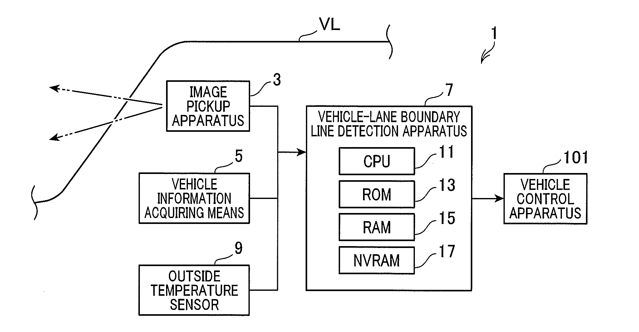
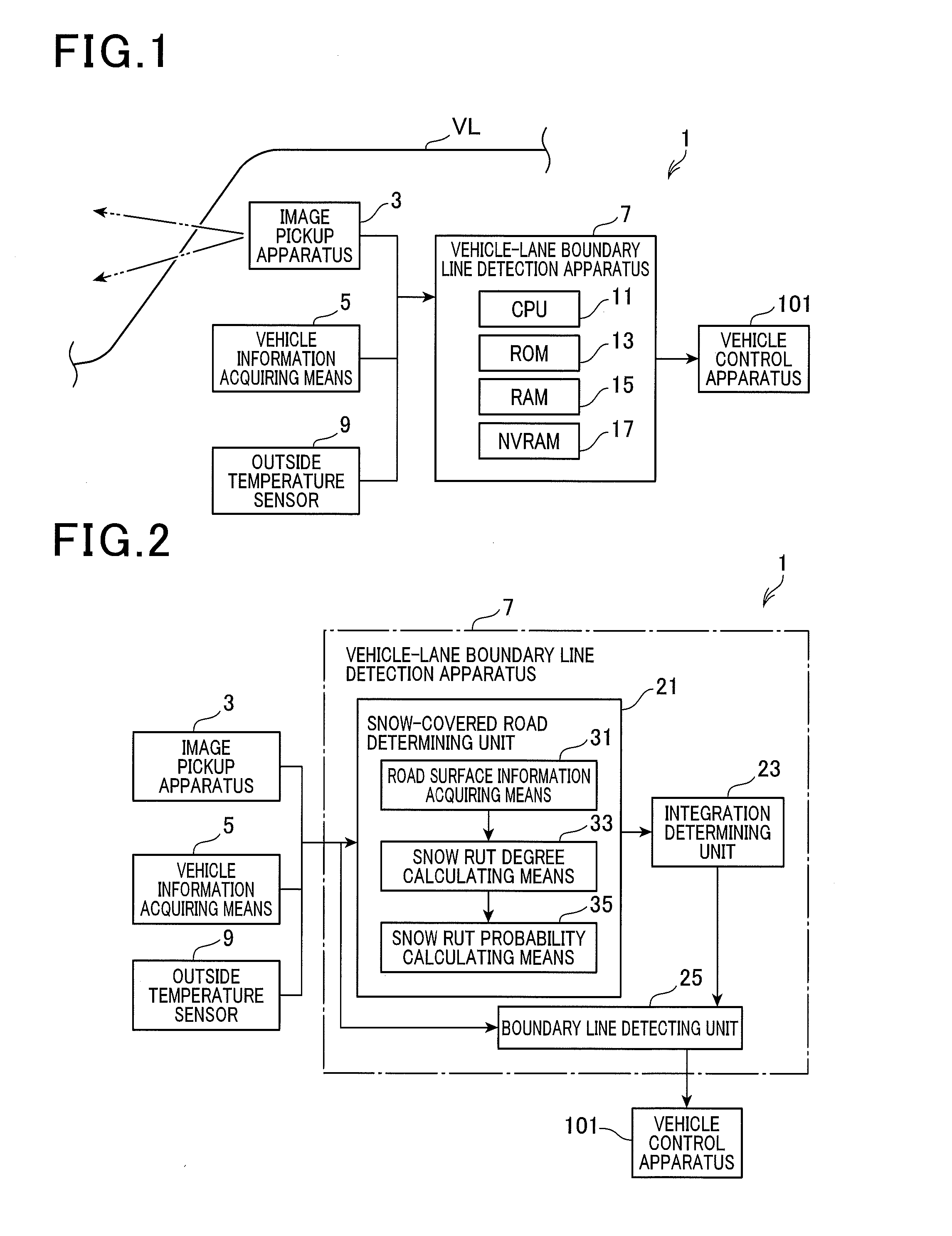
[0034]FIG. 1 describes an overview of a configuration of a vehicle-lane boundary line recognition system 1. The vehicle-lane boundary line recognition system 1 is a system which is used so as to be mounted in a vehicle VL, such as an automobile. As shown in FIG. 1, the vehicle-lane boundary line recognition system 1 includes an image pickup apparatus 3, a vehicle information acquiring means 5, a vehicle-lane boundary line detection apparatus (in other words, an apparatus and a method for detecting a boundary line (boundary or edge on a road surface) of a vehicle lane) 7, an outside temperature sensor 9, and a vehicle control apparatus 101. In other words, the vehicle-lane boundary line detection apparatus 7 of the first example is implemented as an element of the vehicle-lane boundary line recognition system 1. In the description hereafter, the vehicl...

second example

[0079]A vehicle-lane boundary line recognition apparatus of a second example will be described with reference to FIG. 9 and FIG. 10.

[0080]A vehicle-lane boundary line recognition system 61 of the second example has a configuration that is substantially the same as that of the vehicle-lane boundary line recognition system 1 of the first example. However, the functions thereof differ from those of the first example. Therefore, in the second example, elements achieving functions that are the same or similar to those in the first example are given the same reference numbers. Descriptions of sections that are similar to those in the first example are omitted. The modified functions and processes are described below.

[0081]In the vehicle-lane boundary line recognition system 61 of the present example, as shown in FIG. 9, a vehicle-lane boundary line detection apparatus 63 functions as a gravel road detecting unit 65 and a road surface reflection detecting unit 67, in addition to the functi...


PUM


Abstract

In vehicle-lane boundary line detection, low-luminance values are acquired from areas corresponding to below a tire and directly below a vehicle center based on a road surface image. A snow rut degree is calculated based on a luminance ration between the areas. A probability is calculated from a map based on the calculated snow rut degree. A parameter indicating the degree of snow rut likeness is calculated by a low-pass filtering process. A snow rut determination is made by the calculation result being compared with a predetermined threshold. A final determination of whether or not a snow rut is present is made, with reference to an outside temperature. When determined that a snow rut is present, a determination is made not to perform the detection. When determined that a snow rut is not present, a determination is made to perform the detection.

Description

CROSS REFERENCE TO RELATED APPLICATIONS[0001]This application is a U.S. National Phase Application under 35 U.S.C. 371 of International Application No. PCT / JP2013 / 065206 filed on May 31, 2013 and published in Japanese as WO 2013 / 180273 A1 on Dec. 5, 2013. This application is based on and claims the benefit of priority from Japanese Patent Application No. 2012-126154 filed Jun. 1, 2012. The entire disclosures of all of the above applications are incorporated herein by reference.BACKGROUND[0002]1. Technical Field[0003]The present invention relates, in particular, to an apparatus that detects a vehicle-lane boundary line, such as a white line, based on a road surface image capturing a road surface ahead of a vehicle, and a method thereof.[0004]2. Background Art[0005]A vehicle-lane boundary line detection apparatus has been proposed in the past that detects a boundary line of a vehicle lane (hereinafter, a vehicle-lane boundary line), such as a white line, based on a road surface image ...

Claims


Application Information

Patent Timeline
IPC IPC(8): G06K9/00G08G1/16B60R1/00
CPCG06K9/00798G08G1/167B60R1/00G06T7/12G06T2207/30256G06V20/588G06T2207/10024
Inventor ISHIMARU, KAZUHISAKAWASAKI, NAOKISUZUKI, SHUNSUKETAKAFUJI, TETSUYA
Owner DENSO CORP
Why Eureka
Try Eureka