Packaging for transporting and/or storing radioactive material

a technology for radioactive materials and packaging, applied in the direction of portable shielded containers, nuclear elements, shielding, etc., can solve the problems of inability to meet the requirements of the radiation protection structure, inability to meet the requirements, and inability to carry two to three times the weigh

Active Publication Date: 2015-06-18
TN INT (FR)
View PDF4 Cites 2 Cited by
  • Summary
  • Abstract
  • Description
  • Claims
  • Application Information

AI Technical Summary

Benefits of technology

[0036]In another embodiment, the distancing-effect portion comprises structural elements and air. The latter has more than about 70% of the global volume of the distancing-effect portion. The structural elements can be made from polyethylene and more particularly from high density polyethylene. These materials have the advantage of being easily cleaned and disinfected in order to meet in particular the current hygiene constraints imposed in medicine.
[0040]Preferably, in order to improve the distancing effect without excessively increasing the mass of the packaging, the structural elements can include an additional bracing element mounted around the pair of bracing elements with a lateral wall and an abutment that protrudes interiorly from the lateral wall in order to brace the outer bracing element of the pair of bracing elements.

Problems solved by technology

The disadvantage of these packagings is that, in order to respond to the criterion of the dose equivalent rate, they are two to three times heavier than what is recommended in order to be able to be manipulated and transported by a single person.
Another disadvantage of the packagings described in the oldest documents is that they are no longer compliant with the recent operating requirements that aim to reduce as much as possible the dose equivalent rate at the outside of the packaging.
A transposition of their design in order to render them compliant with these operating constraints, more restrictive than the regulatory requirements, would generate a thickening of the radiation protection structure and therefore an inacceptable increase in the mass.
A third disadvantage of these packagings is linked to the hygiene constraints that are inherent in the medical sector.
The choice of certain surface materials is not possible due to their oxidation, by acids or other products used to carry out cleaning, decontamination or disinfection operations.

Method used


Image

  • Packaging for transporting and/or storing radioactive material
  • Packaging for transporting and/or storing radioactive material
  • Packaging for transporting and/or storing radioactive material

Examples


first embodiment

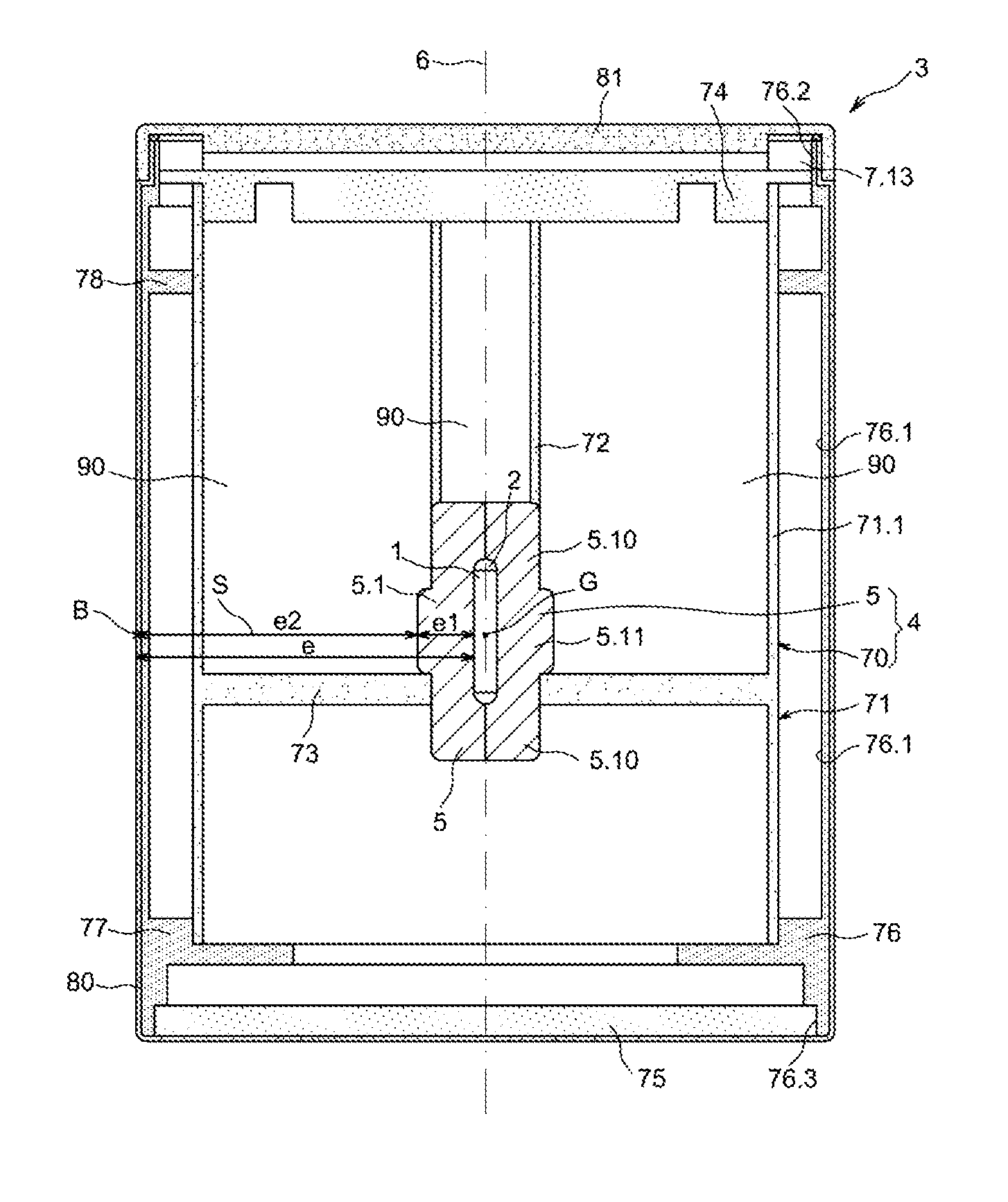
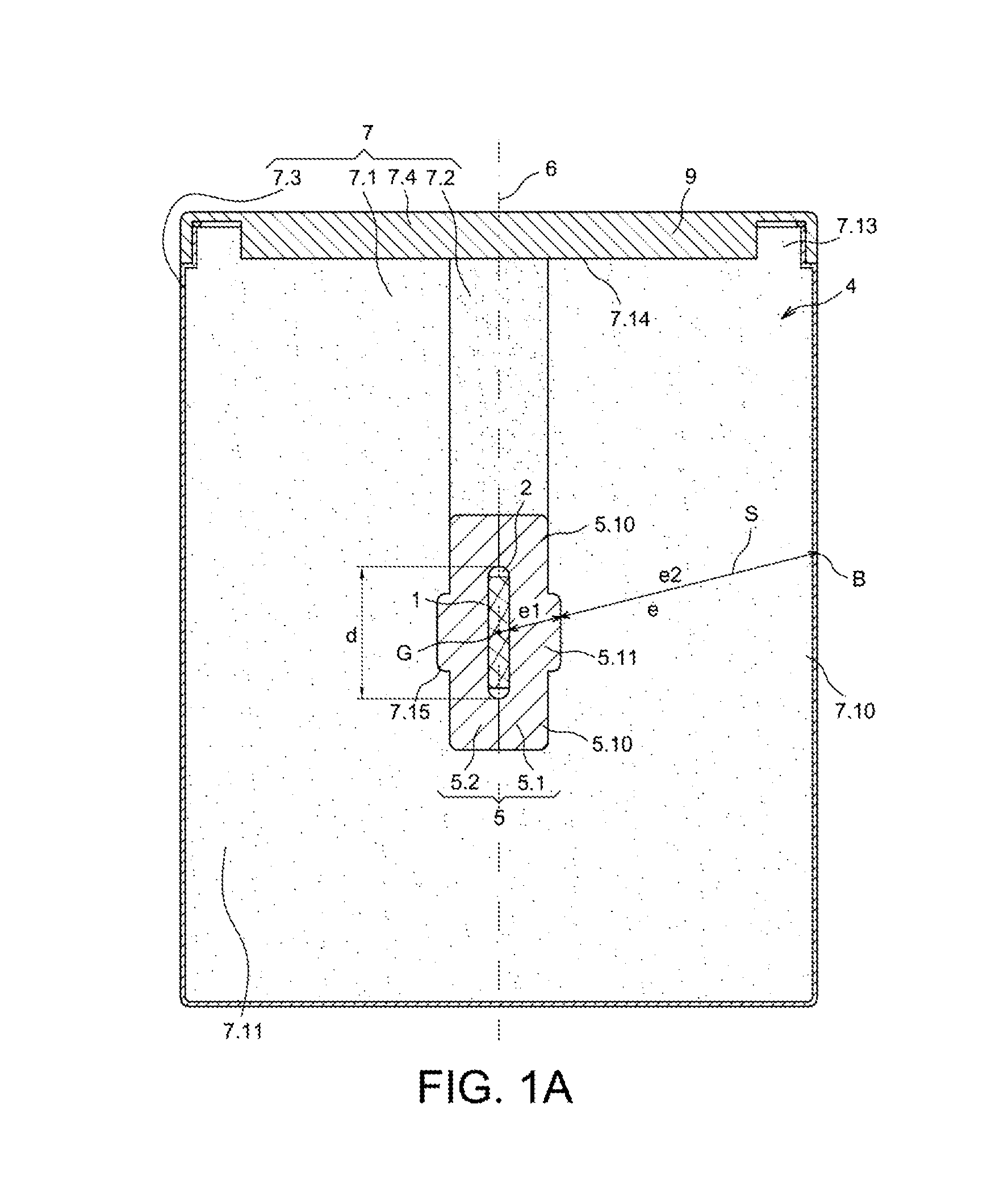
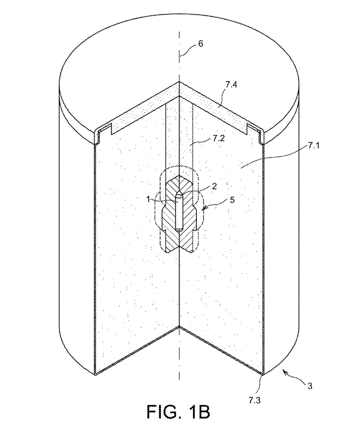
[0046]FIGS. 1A, 1B show respectively as a longitudinal cross-section and as a cut-away three-dimensional view a packaging in accordance with the invention;

[0047]FIGS. 2A1, 2A2, 2B1, 2B2, 2C1, 2C2, 2D1, 2D2 show as a longitudinal cross-section and as a cross-sectional section a plurality of packagings of prior art and according to the invention;

[0048]FIG. 3 is a graph that makes it possible to choose the thickness of the shielding portion and of the packaging in order to meet the criteria of mass and of dose rate;

[0049]FIG. 4 shows as a longitudinal cross-section another embodiment of the packaging according to the invention.

DETAILED DESCRIPTION OF PARTICULAR EMBODIMENTS

[0050]As has just been shown, the object of the invention is to optimize the mass of the packaging while meeting the criterion of dose rate at any point on its outer surface and the mechanical tests provided for by current regulations in terms of transporting radioactive material.

[0051]The underlying idea of the inve...

second embodiment

[0067]In a second embodiment, it can be formed from structural elements that alternate with air in such a way as to reduce the global mass without weakening the mechanical resistance of the packaging 3, as shown in FIG. 4.

[0068]In a first alternative of the first embodiment, on or several of these filling elements are made from a material of which the density is less than 0.5 such as wood, polyurethane foam, phenolic foam. Balsa has a density of a magnitude of 0.1.

[0069]In a second alternative of the first embodiment, one or several of these filling elements have a cell structure of the honeycomb type, of the corrugated cardboard type. In this latter case, the elements always have a density of less than 0.5, but the material from which they are made can have a density of more than 0.5, such as aluminum or cardboard.

[0070]In the example of FIGS. 1A, 1B, first filling elements of the distancing-effect portion 7 take the form of a hollow element 7.1 intended to house the shielding port...


PUM


Abstract

Packaging for transporting radioactive material (1) comprising a radiation protection structure (4) comprising a shielding portion (5) defining a cavity (2) to house the radioactive material and a portion (7) having the effect of distancing the radioactive material from the outside of the packaging. The distancing-effect portion (7) directly encloses the shielding portion (5). The protection structure (4) has a thickness e associated with a segment (S) connecting a point (B) on the outer surface of the packaging to the center of gravity (G) of the cavity (2). It satisfies for any point (B): e=e1+e2 and 0.05<e1 / e<0.25, where e1 is the thickness of the shielding portion (5), e2 is the thickness of the distancing-effect portion (7), with e1, e2 associated with the segment (S). The shielding portion (5) has a mean density of more than 8, the distancing-effect portion has a mean density of less than 0.5.

Description

TECHNICAL FIELD [0001]This invention relates to a packaging for transporting and / or storing radioactive material such as a radioactive source emitting highly energetic ionizing radiation. This ionizing radiation, such as gamma radiation, must be attenuated when the radioactive material is housed in the packaging for transporting and / or storing in such a way as to reduce the exposure of people to ionizing radiation.[0002]More particularly but not exclusively, the invention relates to the transporting and / or storing of radioactive sources, such as radium, of which the application is preferentially an application in the medical field, for a therapeutic purpose.PRIOR ART [0003]In this type of packaging for radioactive source emitting highly energetic gamma radiation, it is sought to combine the criteria of mass and absorbed dose equivalent rate (DER) so that the packaging can be used sustainably by the same operator. The criterion of mass is that the packaging can be manipulated by an i...

Claims


Application Information

Patent Timeline
Patent Type & Authority Applications(United States)
IPC IPC(8): G21F5/06
CPCG21F5/06G21F7/015G21F1/085G21F5/08
Inventor LELEU, GILDAMASSIF, KEVIN
Owner TN INT (FR)
Why Eureka
Try Eureka