Charging apparatus for mobile device

a charging apparatus and mobile technology, applied in electric vehicles, transportation and packaging, transmission, etc., can solve the problems of complex design of non-contact chargers, inability to fix the first connector body, and damage to the connector while being coupled, so as to improve convenience, avoid damage due to frequent mounting, and improve convenience

Active Publication Date: 2015-06-18
SPS CO LTD
View PDF4 Cites 25 Cited by
  • Summary
  • Abstract
  • Description
  • Claims
  • Application Information

AI Technical Summary

Benefits of technology

[0020]According to the present invention, the charging apparatus for a mobile device charges the mobile device by magnetically coupling the mobile device and the charging mount using magnets while mutually matching electrical terminals, improving convenience when charging the mobile device.
[0021]Further, when charging the mobile terminal, the terminal is coupled to the charging mount magnetically rather than mechanically, so that there is no need for separate efforts for coupling using connectors, and damage occurring due to frequent mounting can be fundamentally avoided.
[0022]Further, ...

Problems solved by technology

However, the method of coupling the connectors by fitting the male connector into the female connector may damage the connectors while they are being coupled.
In addition, it is required to find the female connector which is disposed in the mobile device and vertically f...

Method used


Image

  • Charging apparatus for mobile device
  • Charging apparatus for mobile device
  • Charging apparatus for mobile device

Examples


Embodiment Construction

[0030]Hereinbelow, preferred embodiments of the present invention will be described in detail with reference to the accompanying drawings. Wherever possible, the same reference numerals will be used throughout the drawings and the description to refer to the same or like parts. In the following description, it is to be noted that, when the functions of conventional elements and the detailed description of elements related with the present invention may make the gist of the present invention unclear, a detailed description of those elements will be omitted.

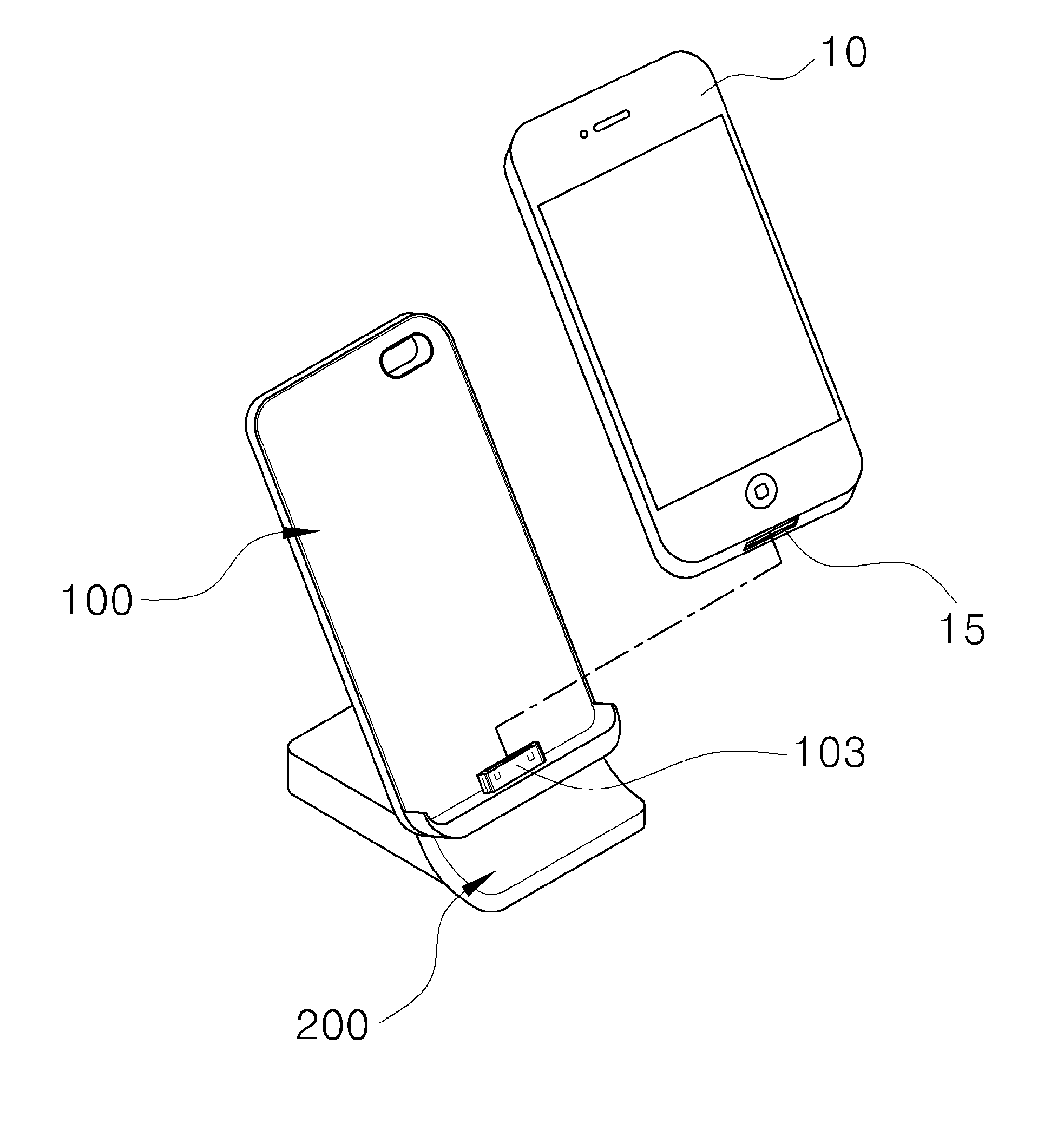
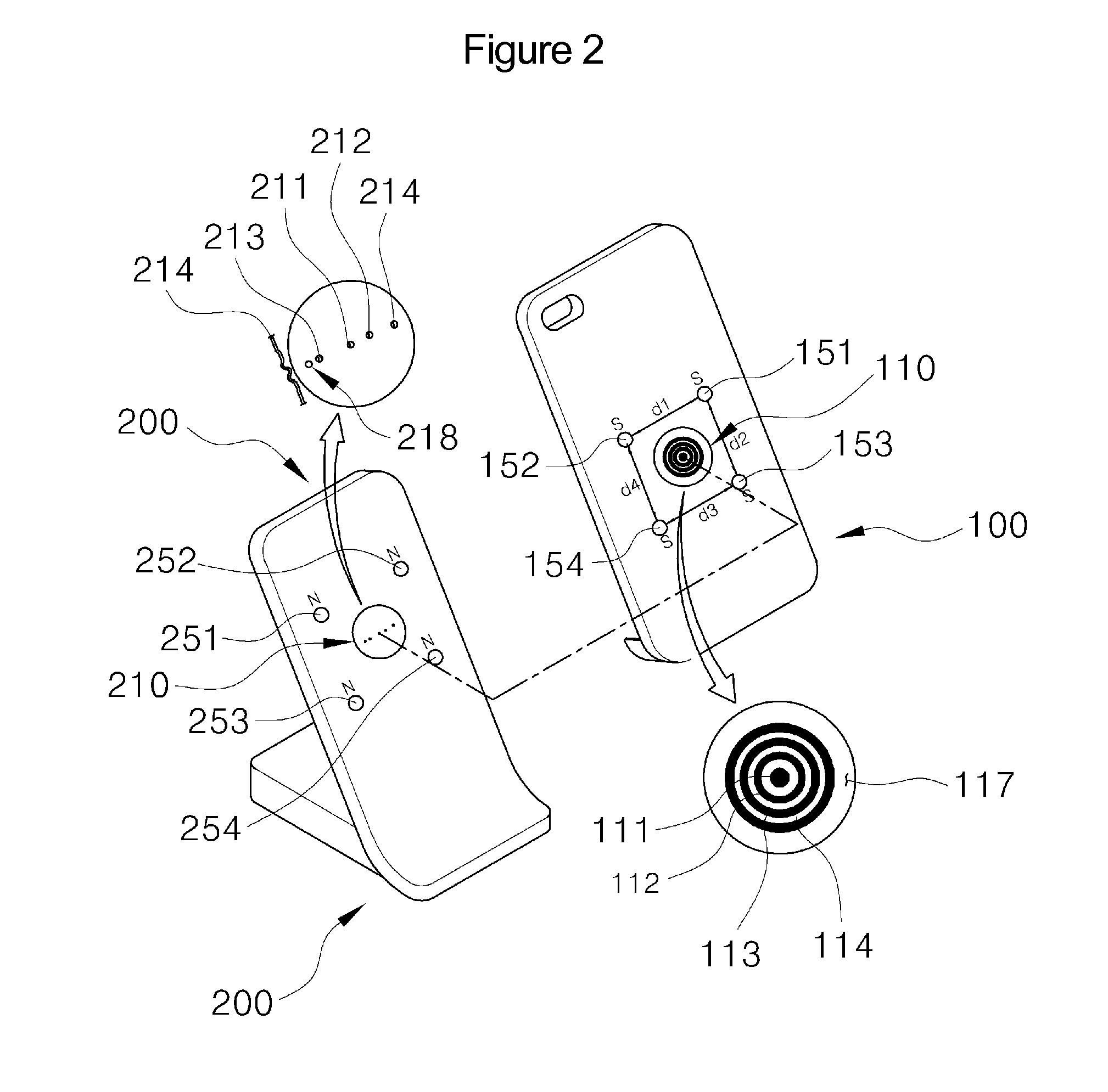
[0031]FIGS. 1 and 2 are views illustrating a charging apparatus for a mobile device according to an embodiment of the present invention, wherein the charging apparatus includes a terminal casing 100 and a charging mount 200.

[0032]The terminal casing 100 is formed of a resilient substrate that is made of a polymer or plastic. The terminal casing includes, at a lower portion, a connector 103 that is to be connected with a charging te...


PUM


Abstract

A charging apparatus for a mobile device is provided. The apparatus includes a terminal casing and a charging mount. A pattern electrode part has concentric electrode patterns. A first magnet is provided underneath the pattern electrode part, and a second magnet having multiple magnet elements is disposed around the pattern electrode part. The charging mount has a pin terminal part which comes into contact with the pattern electrode part. A third magnet being magnetically coupled with the first magnet is provided underneath the pin terminal part. A fourth magnet being magnetically coupled with the second magnet is provided around the pin terminal part.

Description

TECHNICAL FIELD[0001]The present invention relates, in general, to a charging apparatus for a mobile device and, more particularly, to a charging apparatus for a mobile device which charges the mobile device by magnetically coupling the mobile device with a charger using magnets while mutually matching electrical terminals.BACKGROUND ART[0002]Mobile devices such as cellular phones, smart phones and personal digital assistants (PDAs) are widely used since they generally have good mobility and portability. Accordingly, wired chargers for charging batteries of mobile devices are fabricated in different shapes depending on the shapes or standards of batteries which are manufactured for them. In response to trends toward improved performance and lightness of mobile devices which are intended to satisfy consumers' demands, even a single manufacturer fabricates various types of mobile devices and various types of corresponding chargers.[0003]Mobile devices are supplied with direct current ...

Claims


Application Information

Patent Timeline
IPC IPC(8): H02J7/00
CPCH02J7/0044H02J7/00H04B1/38
Inventor KIM, HYUN-JUNYOUN, DAE-YOUNGKIM, JUNG-GYOJEONG, SEUNG-JUKIM, HYO-NAM
Owner SPS CO LTD
Why Eureka
Try Eureka