

Regenerator placement using a polynomial-time algorithm
Patent Information
- Authority / Receiving Office
- US · United States
- Patent Type
- Applications(United States)
- Current Assignee / Owner
- IBM CORP
- Publication Date
- 2015-06-18
- Estimated Expiration
- Not applicable · inactive patent
Smart Images
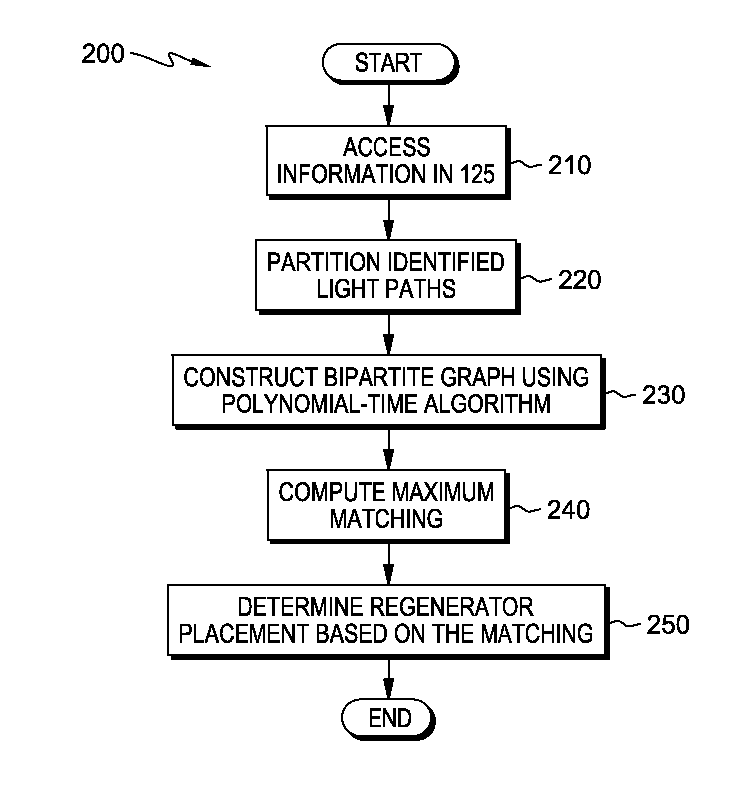
Figure 1 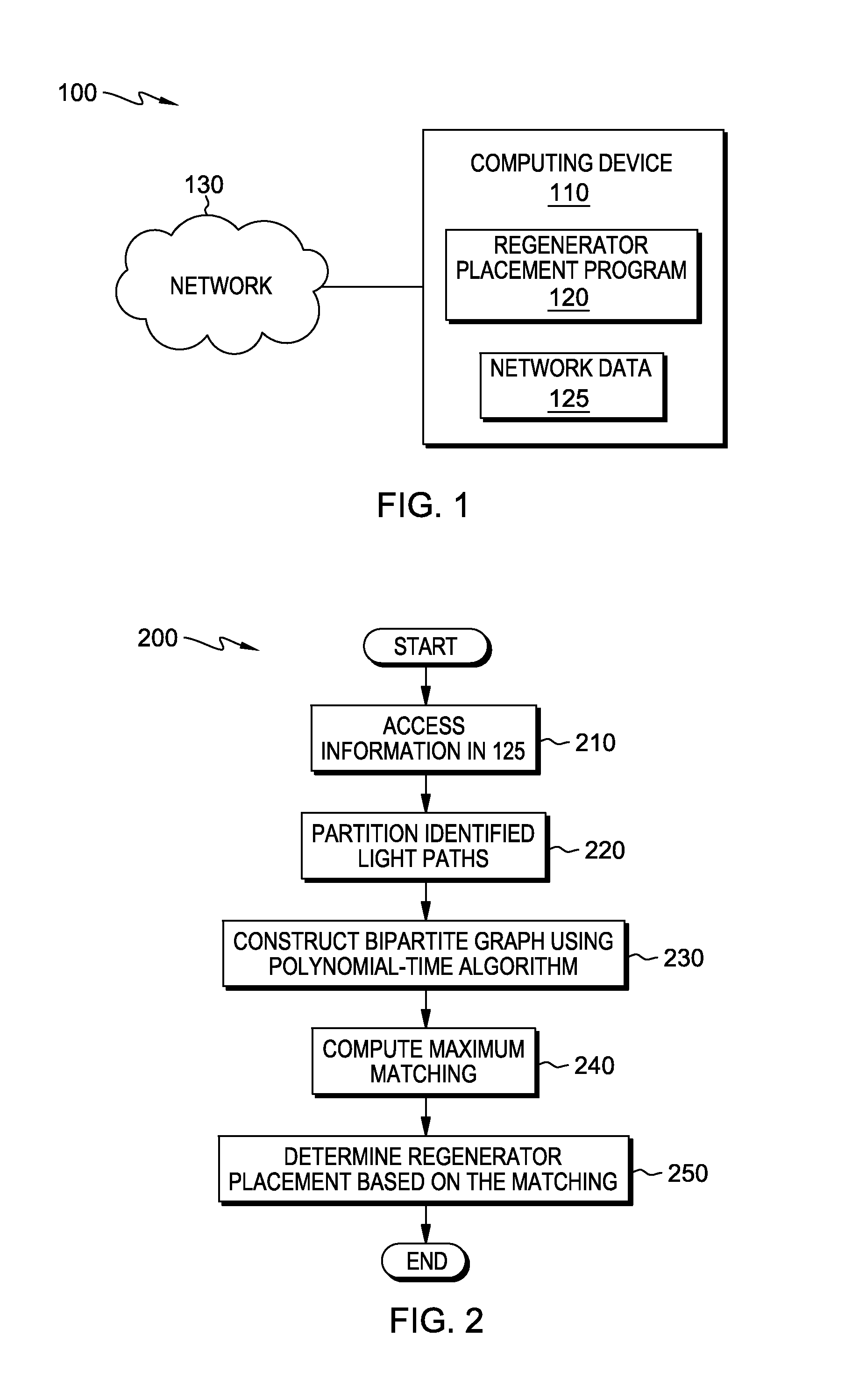
Figure 2 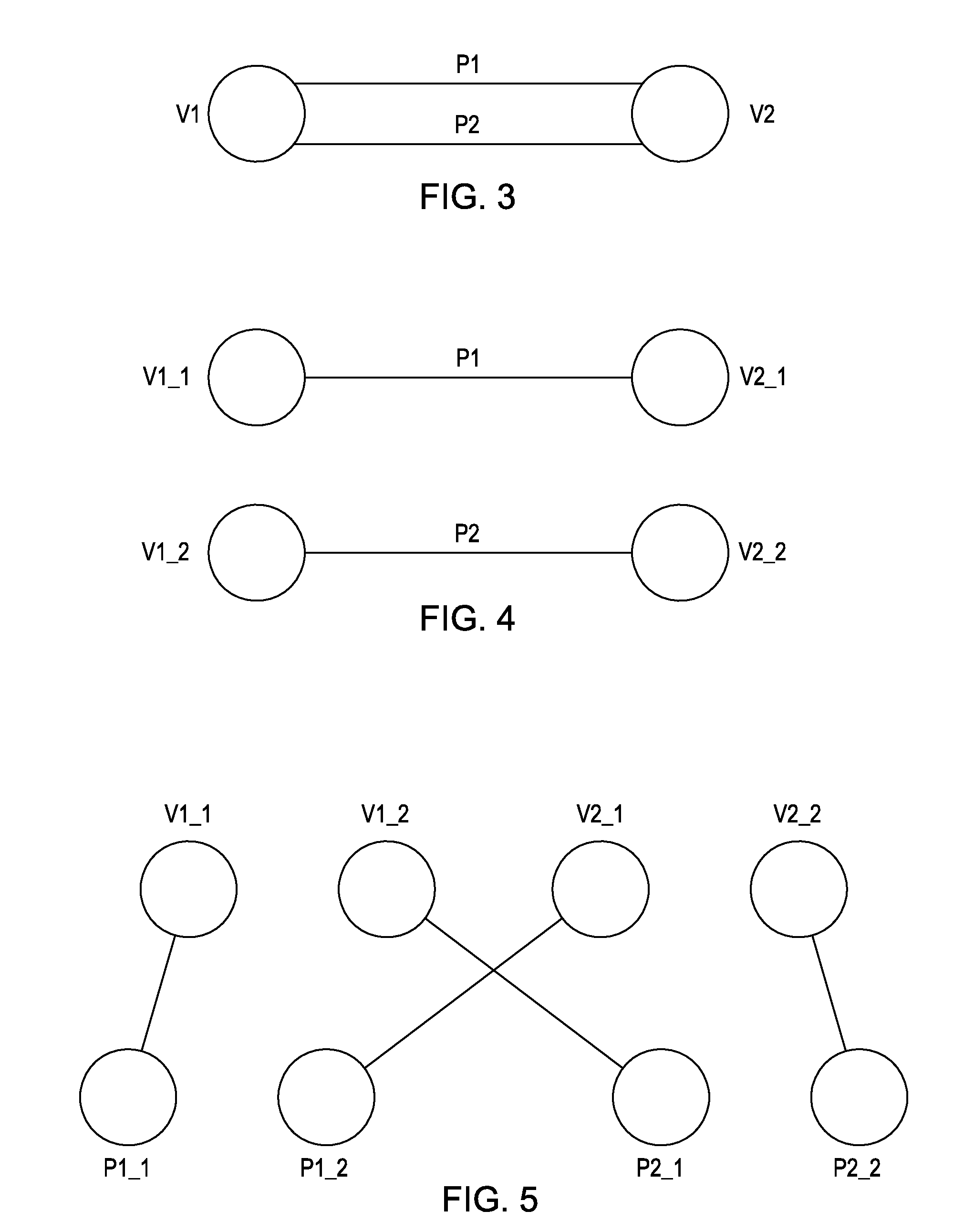
Figure 3
Abstract
Description
FIELD OF THE INVENTION
[0001] The present invention relates generally to the field of optical networking, and more particularly to regenerator placement in optical networks.BACKGROUND OF THE INVENTION
[0002] Fiber-optic communication is a method of transmitting information from one place to another by sending pulses of light through an optical fiber. The light forms an electromagnetic carrier wave that is modulated to carry information. First developed in the 1970s, fiber-optic communication systems have revolutionized the telecommunications industry and have played a major role in the advent of the Information Age. As a result of advantages over electrical transmission, optical fibers have, in many instances, replaced copper wire communications in core networks in the developed world.
[0003] The process of communicating using fiber-optics involves the following basic steps: Creating the optical signal involving the use of a transmitter, relaying the signal along the fiber, ensuring that ...