Apparatuses and Methods for Adjusting the Temperature Inside a Helmet

a technology for helmets and apparatuses, applied in the field of helmets, can solve problems such as brain damage, death or life-long disability, and helmets can pose their own unique problems

Inactive Publication Date: 2015-06-25
GORDON GRANT CHARLES +2
View PDF3 Cites 18 Cited by
  • Summary
  • Abstract
  • Description
  • Claims
  • Application Information

AI Technical Summary

Benefits of technology

[0007]Embodiments of the present helmets can be configured to selectively cool and / or heat the interior of the helmet such that the helmet is suitable for a wide range of activities in varying environmental conditions without compromising the structural integrity of the helmet.

Problems solved by technology

During an impact, a user's brain is particularly susceptible to injury, for example, traumatic brain injury, which can result in death or life-long disability.
While helmets can significantly reduce the risk and / or severity of head injuries, helmets can pose their own unique problems related to the helmet / head interface.
Therefore, depending on the type of helmet and the environment in which it is worn, current helmets can noticeably inhibit a user's ability to regulate their body temperature.
If a user wears such a helmet in a hot climate (e.g., the interior of a racing car), evaporation of perspiration may be inhibited due to the insulating nature of the full helmet and / or helmet padding.
Therefore, such a helmet may make the user may be more susceptible to overheating, dehydration, and / or exhaustion.
However, such air flow channels may make such helmets less desirable in cold environments.
For example, in a cold environment, air flow channels within the helmet may improve convective heat transfer away from the user's head and result in an increased risk for illness, exhaustion and / or hypothermia.
Therefore, a user may be required to wear an additional insulating item underneath the helmet or a different helmet without cooling channels to ensure adequate warmth.
Additionally, cooling vents can compromise the structural strength of a helmet and may be unsuitable for applications requiring full head coverage (e.g., hard hats).

Method used


Image

  • Apparatuses and Methods for Adjusting the Temperature Inside a Helmet
  • Apparatuses and Methods for Adjusting the Temperature Inside a Helmet
  • Apparatuses and Methods for Adjusting the Temperature Inside a Helmet

Examples


embodiment 100

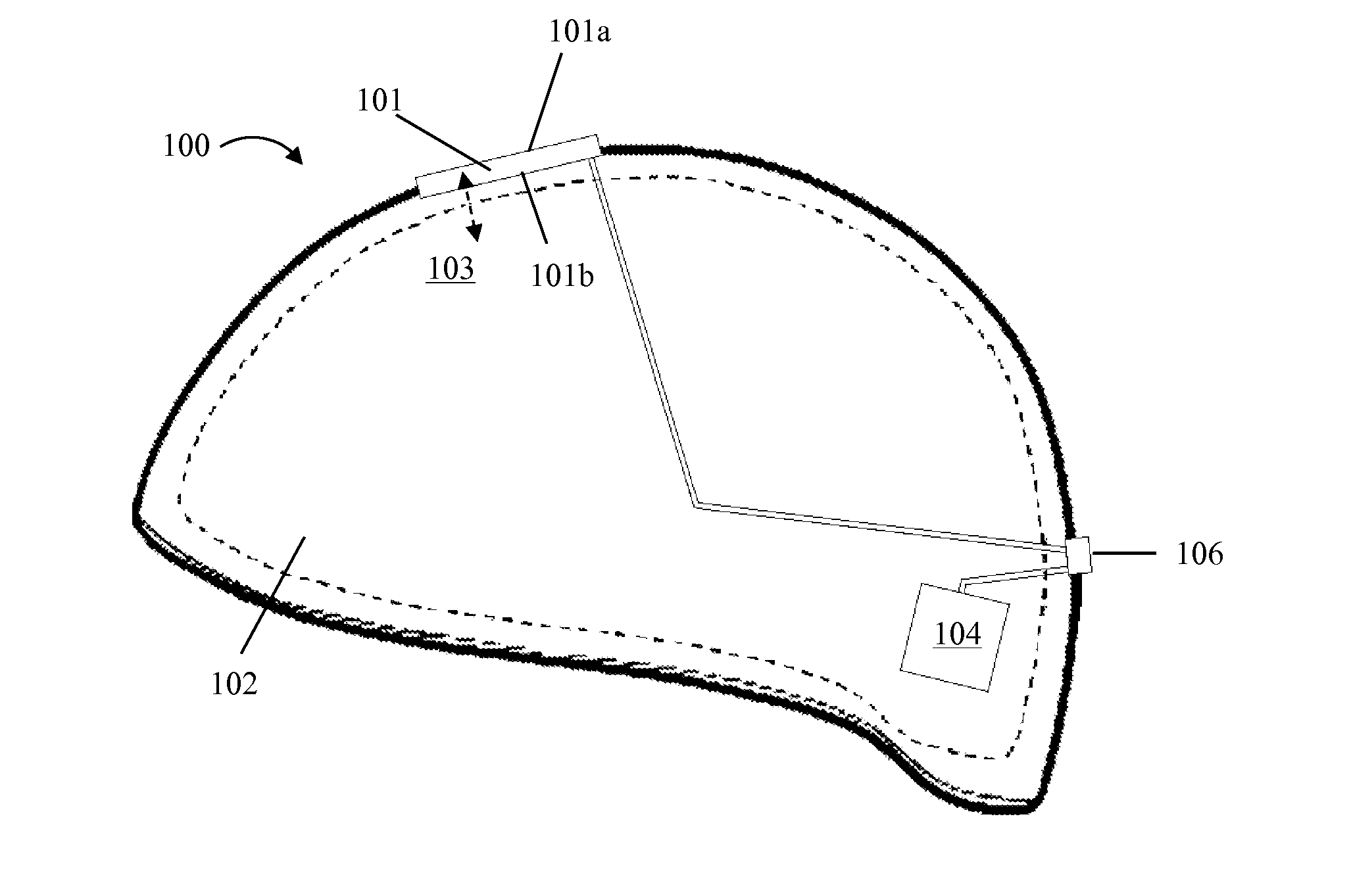
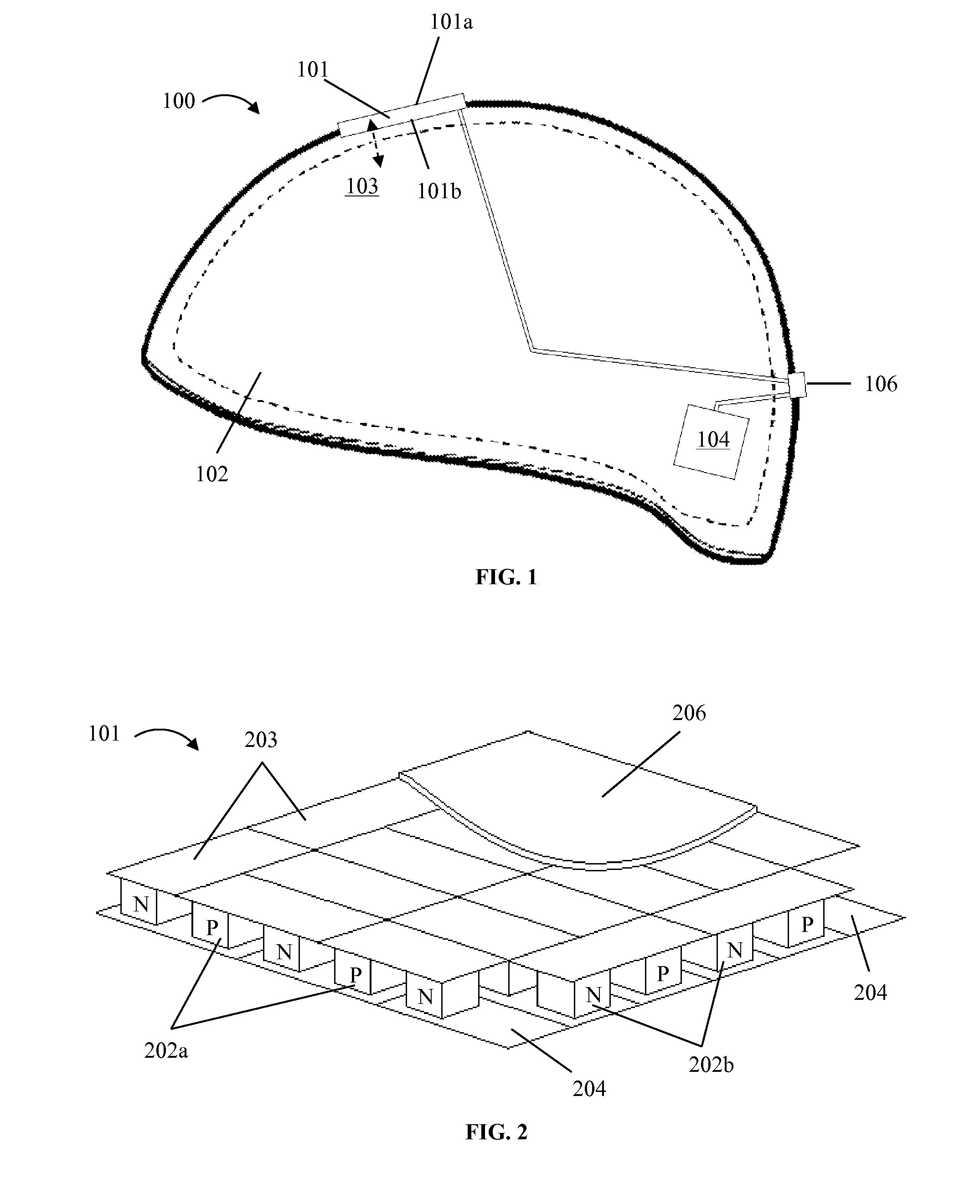
[0025]FIG. 1 depicts an embodiment 100 of the present helmets. Helmet 100 may be any type of helmet configured to be worn by a user, including, but not limited to, a sports helmet (e.g., helmets for football, in-line skating, skate boarding, snowboarding, skiing, and / or biking), a motorsports helmet (e.g., helmets for on-road racing, off-road racing, for use with all-terrain vehicles (ATVs), dirt bikes, and / or four wheelers), a construction helmet (e.g., hard hats), and / or the like. Helmet 100 comprises a thermoelectric element 101 (described in more detail below) having at least one heating surface (e.g., 101a) and at least one cooling surface (e.g., 101b). Helmet 100 further comprises a thermally conductive cloth 102 (described in more detail below) disposed within the helmet and selectively coupled to either heating surface 101a or cooling surface 101b such that the cloth is in thermal communication (e.g., as indicated by arrow 103) with the thermoelectric element. In this embodi...

embodiment 300

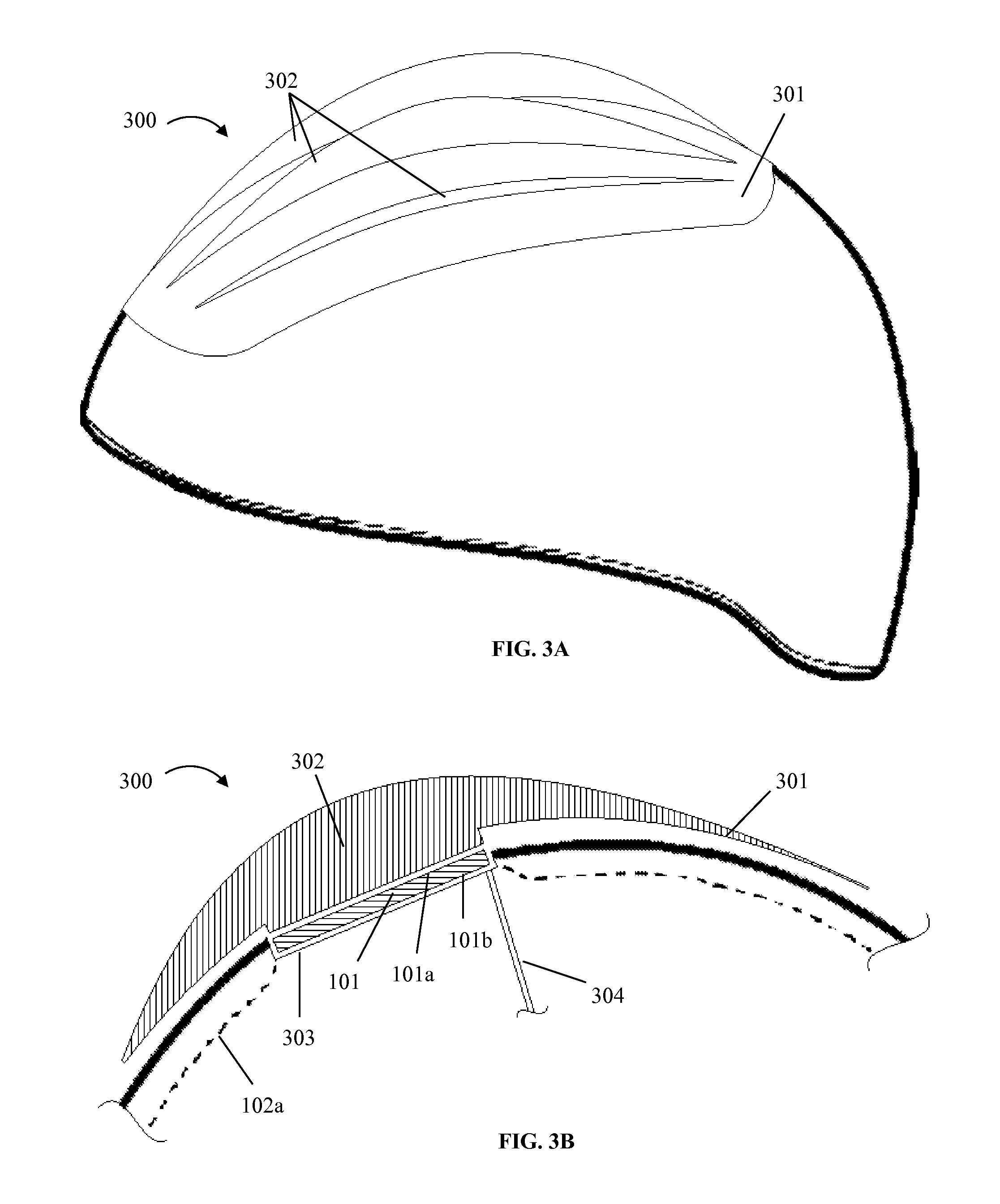
[0029]FIG. 3A depicts another embodiment 300 of the present helmets. Helmet 300 is substantially similar to helmet 100, with the primary exception that an external surface 301 of helmet 300 comprises a plurality of thermally conductive fins 302. Thermally conductive fins 302 may be constructed from a variety of thermally conductive materials, including, but not limited to, carbon fiber, copper, silver, silicon, and / or aluminum. In the embodiment shown, thermally conductive fins are elongated (e.g., having a maximum longitudinal dimension of approximately 70% of a largest corresponding dimension of the helmet), thin, and substantially flat (e.g., having a thickness or transverse dimension of no greater than 5 millimeters (mm)). In this embodiment, thermally conductive fins 302 comprise a small cross-sectional shape when viewed from the front of helmet 300 and thus are capable of transferring a substantial amount of heat to the environment (e.g., through the sides of the fins), withou...

embodiment 400

[0031]FIG. 4 depicts another embodiment 400 of the present helmets. Helmet 400 is substantially similar to helmet 100, with the primary exception that helmet 400 comprises a control circuit 401 in electrical communication with thermoelectric element 101 and power source 104 (e.g., such that control circuit 401 can control the voltage and / or current supplied to thermoelectric element 101 from power source 104). In some embodiments, control circuit 401 comprises a thermostat configured to adjust a temperature inside of the helmet, for example, a bi-metallic strip thermostat. Bi-metallic strip thermostats can comprise two thin strips, each comprising a different type of metal. When the temperature of and / or within the thermostat changes, the differential thermal expansion of the two strips causes the strips to move relative to one another, which can be used to break or complete a circuit (e.g., similar to an on-off switch). Embodiments of the present helmets with control circuits (e.g....


PUM


Abstract

This disclosure includes various helmets that may include: a thermoelectric element having at least one heating surface and at least one cooling surface, a thermally conductive cloth disposed within the helmet and selectively coupled to either the heating surface or the cooling surface such that the cloth is in thermal communication with the thermoelectric element, and a power source. Some of the present helmets include a switch configured to selectively activate or deactivate the thermoelectric element. Others of the present helmets include a plurality of thermally conductive fins disposed on an exterior surface of the helmet.

Description

BACKGROUND[0001]1. Field of Invention[0002]The present invention relates generally to helmets and more specifically, but not by way of limitation, to helmets with adjustable internal temperature (e.g., heating and / or cooling the climate inside a helmet).[0003]2. Description of Related Art[0004]Examples of helmets with mechanisms for adjusting internal temperature are disclosed in U.S. Pat. No. 4,483,021, and U.S. Pat. No. 7,296,304.[0005]During an impact, a user's brain is particularly susceptible to injury, for example, traumatic brain injury, which can result in death or life-long disability. Such brain injuries can occur in various settings, including, but not limited to, sporting activities such as football or automobile racing, recreational activities such as bicycling, and / or occupational activities such as construction work. Typically, helmets are a necessary safety feature for preventing serious injury during such activities, and are often mandated by law. While helmets can ...

Claims


Application Information

Patent Timeline
Patent Type & Authority Applications(United States)
IPC IPC(8): A42B3/04A63B71/10A41D13/005F25B21/04
CPCA42B3/0406F25B21/04F25B2321/02A41D13/0051A41D13/0053A63B71/10F25B2321/023A42B3/285
Inventor GORDON, GRANT CHARLESSHANAHAN, DAVIDLEE, KALEB OMAR
Owner GORDON GRANT CHARLES
Why Eureka
Try Eureka